7–12 469 MOTOR MANAGEMENT RELAY – INSTRUCTION MANUAL
CHAPTER 7: TESTING
S2 SYSTEM SETUP Z CURRENT SENSING Z PHASE CT PRIMARY: “1000”
S2 SYSTEM SETUP ZV VOLTAGE SENSING Z VT CONNECTION TYPE: “Wye”
S2 SYSTEM SETUP ZV VOLTAGE SENSING ZV VOLTAGE TRANSFORMER RATIO: “10.00:1”
Z Inject current and apply voltage as per the table below.
Z Verify accuracy of the measured values.
Z View the measured values in:
A2 METERING DATA ZV POWER METERING.
7.3.3 Unbalance Test
The 469 measures the ratio of negative sequence current (I
2
) to positive sequence current
(I
1
). This value as a percent is used as the unbalance level when motor load exceeds FLA.
When the average phase current is below FLA, the unbalance value is de-rated to prevent
nuisance tripping as positive sequence current is much smaller and negative sequence
current remains relatively constant. The derating formula is:
(EQ 7.1)
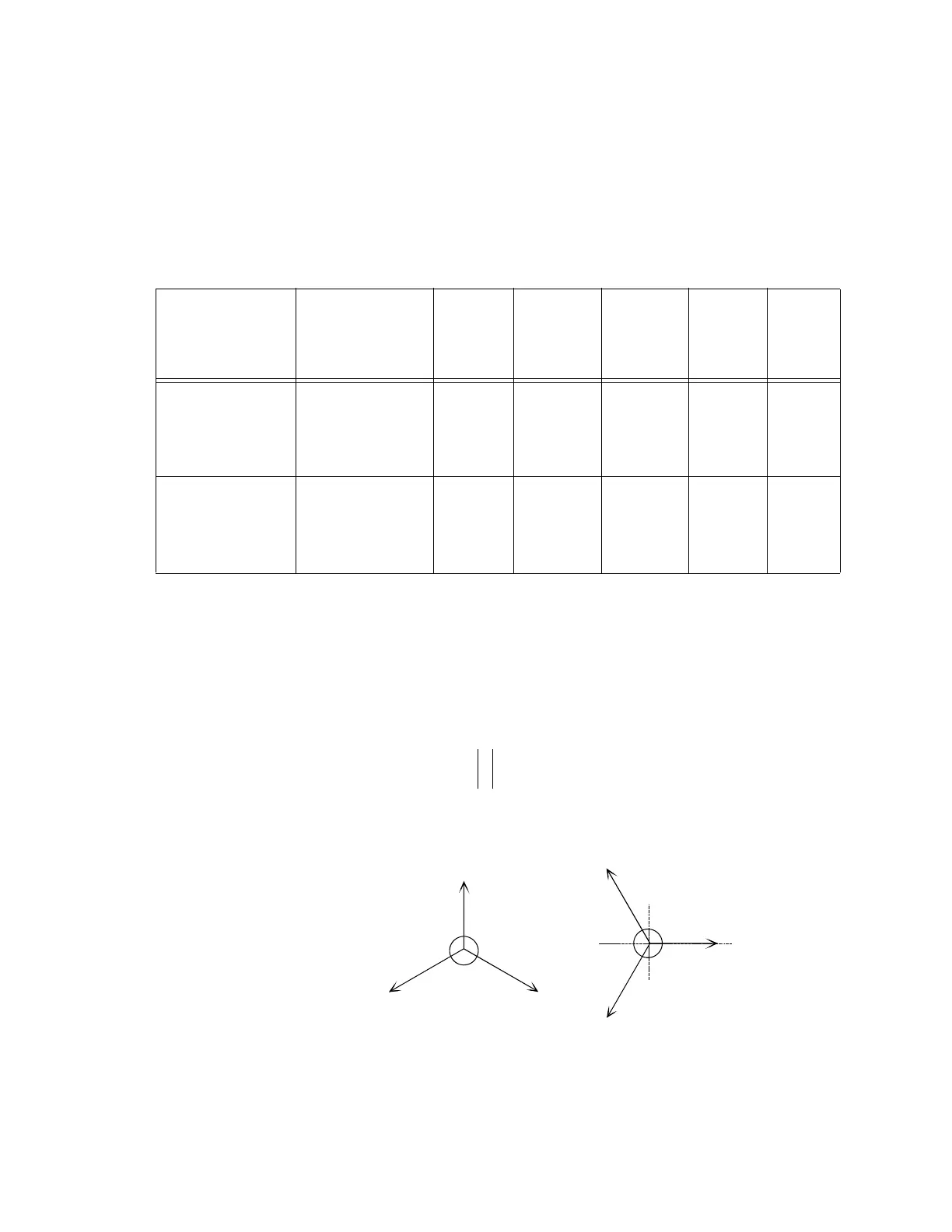
FIGURE 7–2: Three Phase Example for Unbalance Calculation
Symmetrical component analysis of vectors using the mathematical vector convention
yields a ratio of negative sequence current to positive sequence current as shown:
INJECTED
CURRENT 1A
UNIT, APPLIED
VOLTAGE (Ia is the
reference vector)
INJECTED
CURRENT 5A
UNIT, APPLIED
VOLTAGE (Ia is the
reference vector)
EXPECTE
D LEVEL
OF
POWER
QUANTIT
Y
TOLERAN
CE RANGE
OF POWER
QUANTITY
MEASURE
D POWER
QUANTIT
Y
EXPECT
ED
POWER
FACTOR
MEASURE
D POWER
FACTOR
Ia = 1 A ∠0°
Ib = 1 A ∠120°
Ic = 1 A ∠240°
Va = 120 V ∠342°
Vb = 120 V ∠102°
Vc = 120 V ∠222°
Ia = 5 A ∠0°
Ib = 5 A ∠120°
Ic = 5 A ∠240°
Ia = 120 V ∠342°
Vb = 120 V ∠102°
Vc = 120 V ∠222°
+ 3424 kW
3329
to
3519
kW
0.95 lag
Ia = 1 A ∠0°
Ib = 1 A ∠120°
Ic = 1 A ∠240°
Va = 120 V ∠288°
Vb = 120 V ∠48°
Vc = 120 V ∠168°
Ia = 5 A ∠0°
Ib = 5 A ∠120°
Ic = 5 A ∠240°
Va = 120 V ∠288°
Vb = 120 V ∠48°
Vc = 120 V ∠168°
+ 3424
kvar
3329
to
3519
kvar
0.31 lag
I
2
I
1
----
I
avg
FLA
---------
100%××
Ia=780A
@ 0°
Ib=1000A
@ 113°
Ic=1000A
@ 247°
Ia=780A
@ 0°
Ib=1000A
@-113°
Ic=1000A
@ 113°
POWERSYSTEM
VECTOR
CONVENTION
MATHEMATICAL
VECTOR
CONVENTION
 Loading...