GE HEALTHCARE
D
IRECTION 5305880-100, REVISION 3 LOGIQ™ 100 PRO SERVICE MANUAL
Chapter 4 - Functional Checks Page 4-9
Section 4-4 Diagnostics
The LOGIQ™ 100 PRO System service diagnostics comprises of:
1.) Self test or power on diagnostics
2.) Service diagnostic tools
The self test or power on diagnostics are run every time the system is booted. The service
diagnostic tools include test procedures for testing the system at PCB level as well as block level.
The diagnostic tools provides a pop-up menu to enable selection of various tests to test various
blocks on the system.
4-4-1 Power On Diagnostics
The power on diagnostics or self tests are run every time the system is booted. This self tests
include testing the validity of the system software through EPROM checksum test and testing the
system RAM. It checks whether the keyboard and the trackball are properly interfaced to the
system. It also initiates the self test of analog subsystem. The two LED's and the beeper are used
to indicate error conditions.
Note: Power on Diagnostics works only when the system is in application (imaging) mode
and not while on service diagnostics.
4-4-2 Service Diagnostics
For More Details on Service Diagnostic refer Chapter 7.
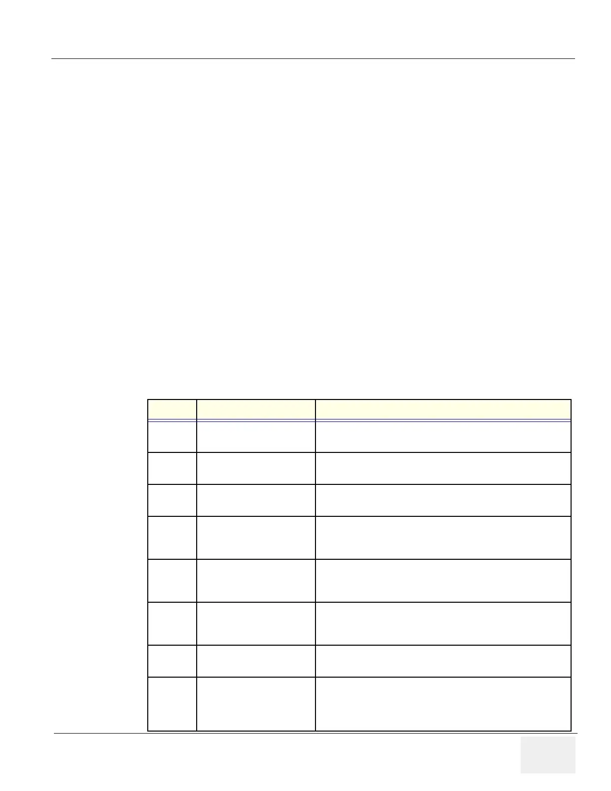
PCB LED Location Function
FEB
LED - Location on FEB
D65
This LED indicates the scan lines,the DSP is scanning.The
LED glows when the cursor is moved in the B/M mode
FEB
LED - Location on FEB
D66
This LED indicates the probe connect signal is good.This
indicates the FEB is Good
FEB
LED - Location on FEB
D67
This LED indicates the B mode signal is given to the
display.The intensity of this LED is more during B mode.
FEB
LED - Location on FEB
D68
This LED indicates the M mode signal is given to the
display.This LED glows during M and B/M mode,the intensity
of this LED is less during B/M mode
DAVINCI
LED - Location on Davinci
CPU D12
This LED is ON during Acoustic Frame measurement
switching.This also indicates the communication between the
DSP and the Davinci CPU FPGA
DAVINCI
LED - Location on Davinci
CPU D11
This LED indicates the Video Sync is happening.This indicates
the video frame output from the Davinci CPU to the monitor is
ok.
DAVINCI
LED - Location on Davinci
CPU D10
This LED indicates the KEY press on the keyboard.It glows
intermittantly when there is a key pressed.
DAVINCI
LED - Location on Davinci
CPU D09
This LED indicates the USB connection to the
Rearpanel.When a USB device or Pen drive is connected, the
LED glows to indicate it is to the Davinci CPU.(USB output of
the Davinci is Good)
State: RELEASE - Document is released and under formal Change Control. Changes are subject to the ECR/ECO Process.
See the GEHC Myworkshop System to determine the status of this document.
Approved Document - 5305880-100TPH_r3.pdf Page 84 of 197
 Loading...


