GE HEALTHCARE
D
IRECTION 5305880-100, REVISION 3 LOGIQ™ 100 PRO SERVICE MANUAL
Chapter 4 - Functional Checks Page 4-11
Section 4-7 Patient contact tools
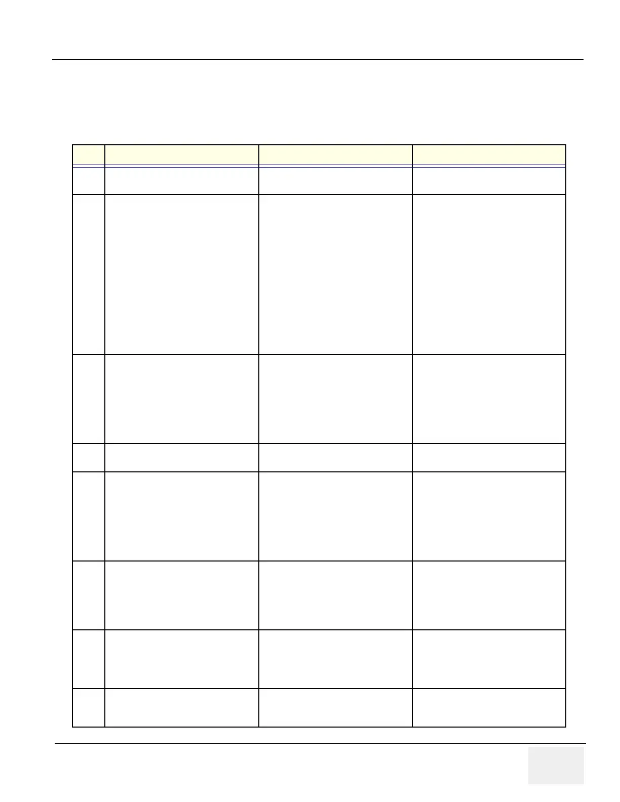
4-7-1 Probe/Connectors Check
Take the probes and check them as described below:.
Step Check Expected Result(s) If Not Remedy
1. To test each delivered Probe, Connect it
to the System
It will display the probe name on the
screen
2. Hold the probe connector horizontally
with the cable pointing Sideways.
Turn the connector locking handle to the
Vertical position.
Align the connector with the probe port
and carefully push into place.
Rotate the locking handle to the full
Horizontal position to lock in place.
Position the probe cable so that it is not
resting on the floor
CAUTION:
Do not allow the probe head to hang
freely. Impact to the probe head may
result in irreparable damage.
To connect a probe:
3. Rotate the lock handle counter-
clockwise to the Vertical position to
unlock the connector.
Remove the connector from the port
Ensure that the probe head is clean
before placing the probe in its storage
case.
To disconnect probes:
The probes that are not connected
to the unit should be stored in their
storage case.
4. To test the Two Probe Adapter,
Connect it to the System
To connect to the probe port
5. Hold the Two Probe Port connector
horizontally
Turn the connector locking handle to the
Vertical position.
Align the connector with the probe port
and carefully push into place.
Rotate the locking handle to the full
Horizontal position to lock in place.
To connect a probe:
6. Two Probes can be Switched by
pressing the Key on the Two Probe Port
The LED toggles to indicate the probe
change & a click is also heard to
indicate change over
The system initalizes the new probe &
the image from the newly selected
probe is displayed in the B-Mode
7. Presetting Parameters to a Probe,
Select the desired probe & adjust the
desired parameters
Press CTRL + W + Enter
The Parameters selected will be set as
Default Values
8. To test the LOGIQ PROBE ADAPTER,
connect it to the system
Connect the Adapter to the Port
Table 4-5 Probe and connectors check
State: RELEASE - Document is released and under formal Change Control. Changes are subject to the ECR/ECO Process.
See the GEHC Myworkshop System to determine the status of this document.
Approved Document - 5305880-100TPH_r3.pdf Page 86 of 197
 Loading...


