GE MEDICAL SYSTEMS
D
IRECTION 2300000, REVISION 1 LOGIQ™ 5 SERVICE MANUAL
Chapter 5 Components and Functions 5 - 15
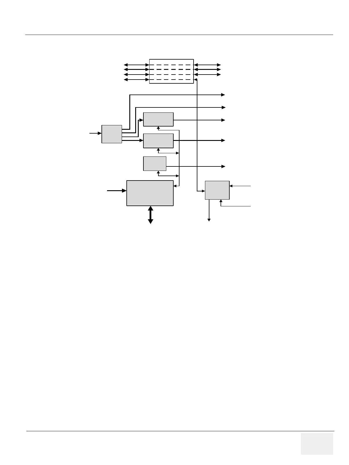
5-5-2 VIC Card
VIC Card perform video conversion operations and Power on/off control.
• Video Decoder : Video decoder convert S-VHS or composite video analog signal to digital RGB data
and send the RGB digital data into BEP main memory on motherboard through PCI bus. And then
this video digital data is displayd on console monitor. Video analog signal comes from rear panel.
This video decoder also have IIC bus interface logic.
• VGA to TV Convertor : This device convert the VGA display signal to TV display signal for B/W
printer and color printer and VCR recording.
• Shutter Control CPLD : Shutter signals for analog B/W printer and color printer are generated by
this CPLD. And this CPLD is controlled by video decoder via IIC bus.
• Power Control FPGA : This FPGA generates power on/off signal. This device is alive always by live
DC power which comes from JPC assy in AC Power Assy. So this device monitor the ststus of
power on/off switch on the keyboard. If power switch will be pushed once, this device turn on the
LV power supply in AC power assy and after few seconds, turn on the BEP assy.
5-5-3 Patient I/O (Option)
The optional Patient I/O is mounted at the front of the BEP chassi.
Available inputs:
•PCG
•ECG
•AUX1
•AUX2
Figure 5-13 VIC Card
Control
FPGA
Video
Decoder
&
PCI I/F
S-VHS /Composite
from Rear panel for
VCR Playback
VGA to TV
Converter
VGA to TV
Converter
Buffer
VGA Signal
(R/G/B/Sync)
To Console
Monitor
External VGA Port
in Rear Panle
BW Image Printer
Color Image Printer
S-VHS /Composite
For VCR Recording
PCI Slot In
BEP Assy
IIC BUS
Shutter
Control
Shutter Sig. for BW/CL Printer
Live DC 5V power
from JPC in AC
Power Assy
Power On/Off signal
from Keyboard assy
Connect to power
on/off pin on
motherboard
2 ports of rs232
Patient IO Interface
IIC BUS Signal
LV Power on/off sig.
To Rear Panel for remote control of VCR
To Patient IO module in BEP Box
To Rear Panel for EEPROM I/F
50p Connector
 Loading...


