GE MEDICAL SYSTEMS
DIRECTION 2300000, REVISION 2 LOGIQ™5 SERVICE MANUAL
8-2 Section 8-3 - Monitor
Section 8-3
Monitor
8-3-1 CRT Assy
Purpose: This is a description on how to remove and replace the CRT Assy.
8-3-1-1 Tools
• Common pillips screwdrivers
• Allen/Unbraco wrench
8-3-1-2 Needed Manpower
• 2 persons, 5 minutes + travel
8-3-1-3 Preparations
• Shut Down the System and switch off the Main Breaker at the rear as described in section 4-3-2 on
page 3.
• Maneuver Control Console to a suitable position for removing the monitor.
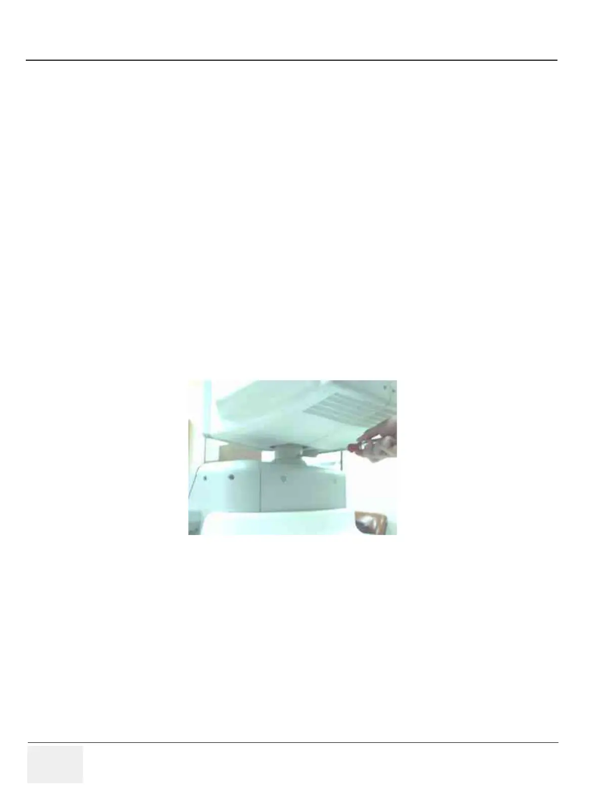
8-3-1-4 Removal procedure
1.) Remove the OP Rear Cover. Refer to section 8-5-10 on page 56.
2.) Unscrew one screw cap located at (1).
Figure 8-1 Removing OP rear Cover and Unscrew screw
(1)
 Loading...


