GE MEDICAL SYSTEMS
D
IRECTION 2300000, REVISION 1 LOGIQ™ 5 SERVICE MANUAL
Chapter 3 Installation 3 - 19
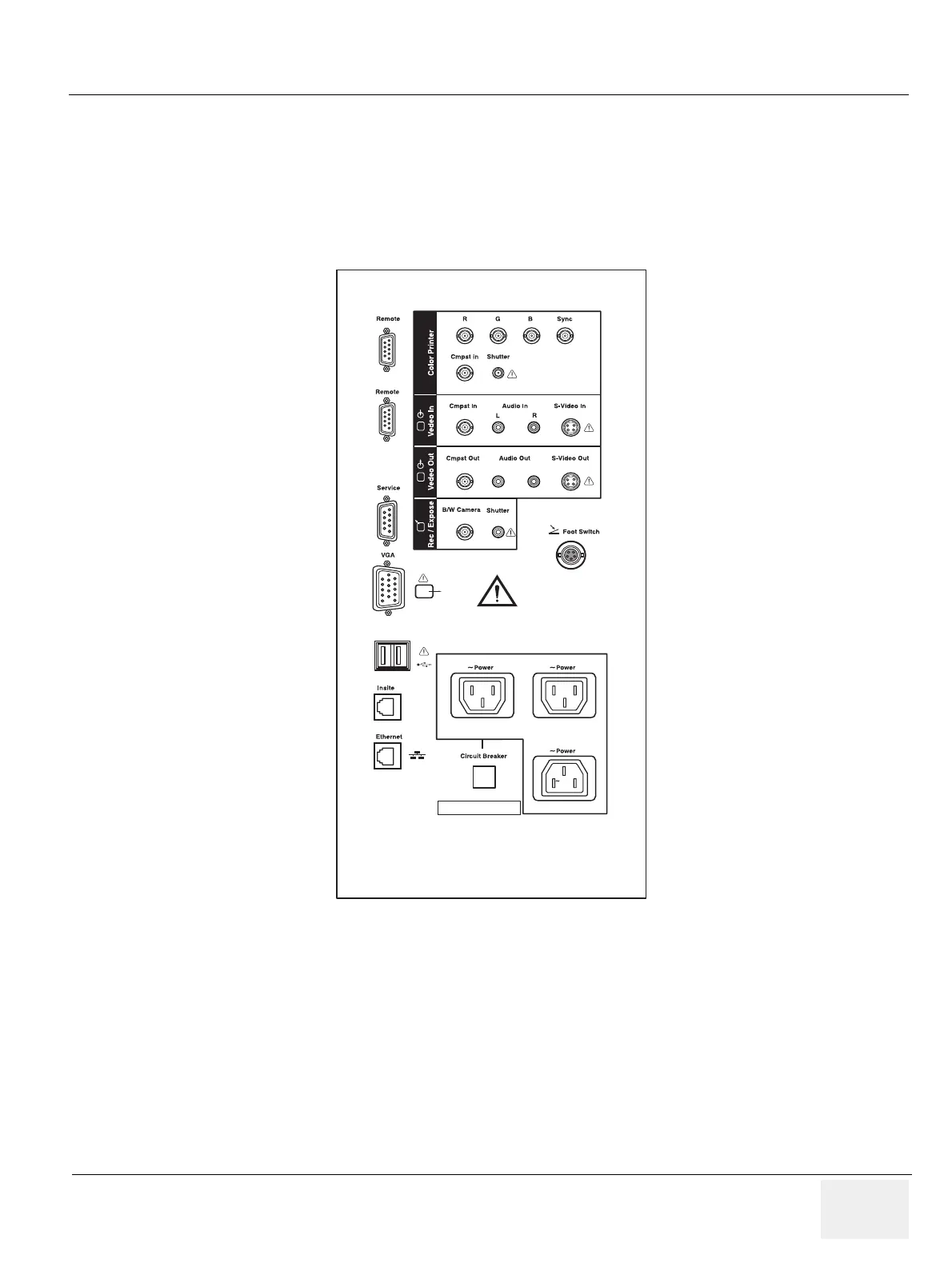
3-6-4 External I/O Connector Panel
Located on the rear panel are video input and output connectors, audio input and output, camera
expose connectors, footswitch connector power connector and control connections for VCR, printer,
and service tools.
This section indicates the pin assignment for each connector.
NOTE: Each outer (case) ground line of peripheral/accessory connectors are protectively grounded.
Signal ground lines are not isolated, except the Service port (3). All of signal lines (include signal
GND) of the Service port are isolated.
Figure 3-21 Rear Connector Panel
220-240V 500VA Max
Including front printer panel
1
2
Serial
1 2
 Loading...


