GE MEDICAL SYSTEMS
D
IRECTION 2300000, REVISION 2 LOGIQ™5 SERVICE MANUAL
Chapter 8 Replacement Procedures 8-101
Section 8-8
PC Block
8-8-1 BEP (Back End Processor - BEP1, BEP2, BEP3, BT05 BEP3,BEP4) ASSY
Purpose: This is a description on how to remove and replace the Parts in the BEP, BEP2 and BEP3
Assy.
NOTE: All BEP, BEP2 and BEP3 and commonly named as “BEP” in this procedure.
8-8-1-1 Tools
• Common pillips screwdrivers
8-8-1-2 Needed Manpower
• 2 persons, 15 minutes + travel
8-8-1-3 Preparations
• Shut Down the System and switch off the Main Breaker at the rear as described in section 4-3-2 on
page 3.
• Left Cover, Right Cover and Rear Cover should be removed before proceed. Refer to section 8-5-
1 on page 39, section 8-5-2 on page 41, and section 8-5-3 on page 43.
8-8-1-4 General Procedures of BEP2 Assy Disassembly
8.) Open the EMI Cover L Assy.
9.) Open the rear cover and EMI Rear Bracket.
10.)Disconnect all the connectors connected With the BEP.
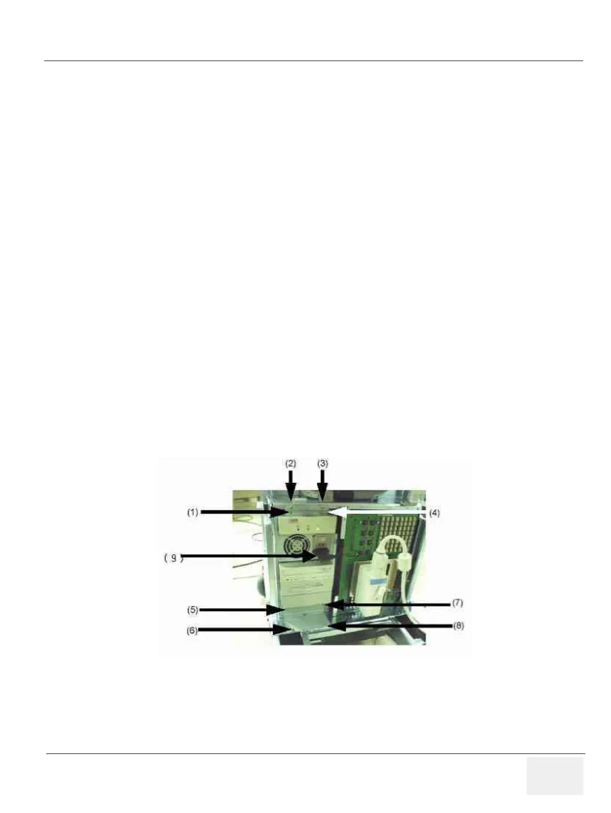
11.)Unscrew eight (8) screws (1-8) and take out the BEP Power plug( 9 ).
12.)Take out the BEP assy to forward direction.
Figure 8-98 Take out the BEP assy from the console
 Loading...


