GE MEDICAL SYSTEMS
D
IRECTION 2300000, REVISION 2 LOGIQ™5 SERVICE MANUAL
Chapter 8 Replacement Procedures 8-15
Section 8-4
Keyboard Block
8-4-1 KeyBoard Assy
Purpose: This is a description on how to remove and replace the Keyboard Assy.
8-4-1-1 Tools
• Common pillips screwdrivers.
8-4-1-2 Needed Manpower
• 1person, 15 minutes + travel
8-4-1-3 Preparations
• Shut Down the System and switch off the Main Breaker at the rear as described in section 4-3-2 on
page 3.
8-4-1-4 Removal Procedure
1.) Remove the Probe Holder. Refer to section 8-4-3 on page 20.
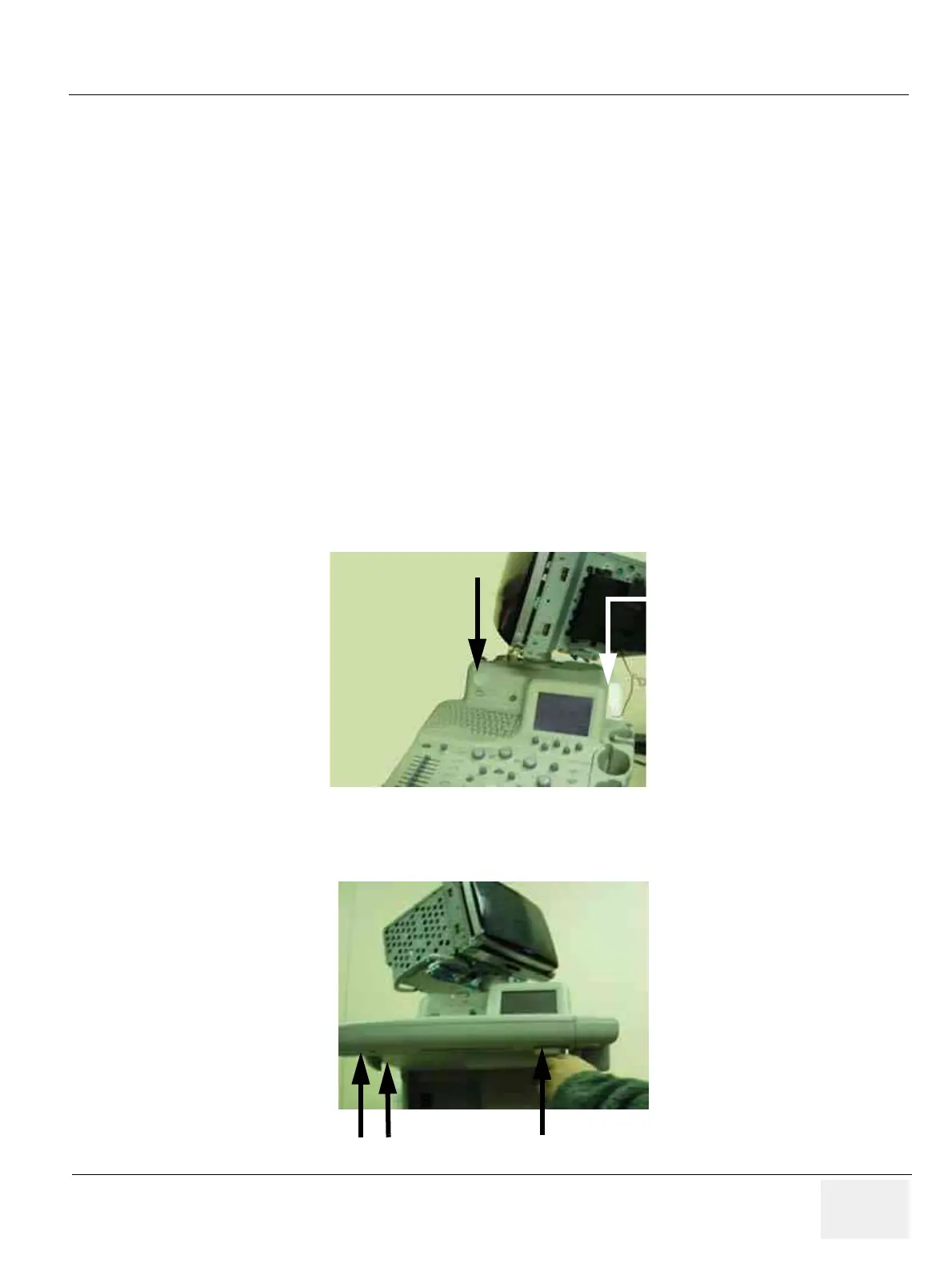
2.) Unscrew two screws (1-2) from the upper side of the keyboard. Refer to Figure 8-18.
3.) Unscrew three screws (3-5) from the bottom of the keyboard. Refer to Figure 8-19.
Figure 8-18 Unscrew two screws on the shoulder
Figure 8-19 Unscrew 3 screws from the bottom
2
1
34
5
 Loading...


