Block Diagram and Theory
LOGIQ e – Basic Service Manual 5-3
5461614-100 English Rev. 6
Block Diagram and Theory
Contents in this Section
• ‘Block Diagram’ on page 5-3
• ‘General Information’ on page 5-4
• ‘Top Console’ on page 5-4
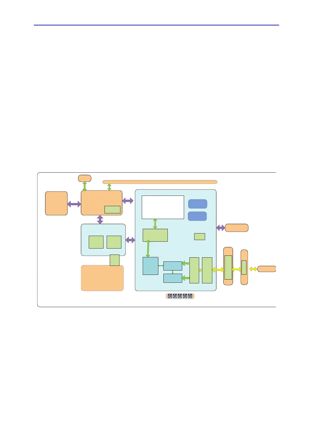
Block Diagram
Figure 5-1. LOGIQ e System Block Diagram
Full S ys
L6IO
WMST:GFI+TRX128
Pulsers
x128
AFE
x128
FPGA
BF64
Battery pack (8 cells)
L6WDC
Ch
ar
ge
r
a
n
d
Switch
HVPS
Use
r
Po
r
ts
mS AT A
SS
D
COM-E module
Intel
M
obile C P
U
261
0
u
@
25
W
i7
@
2
c
ore, 2 thread
BGA Conn
.
FP
G
A
M
id-
Pro
ces
si
ng
DS P
@Br
i
d
g
e
C
O
N
N
L6LCD Panel
LVPS
R
F
data&
SCI
P
CI
-E
EMIF
TEE
F
P
G
A
B
F64
L6PFPC
R
S
128
LVDS
CONN
C
o
n
n
CONN
L6CWD(OPT)
SD CARD
C
ONN
L6DOCKING
CART
CON
N
L6MultPort
C
o
n
n
KBD
CONN

 Loading...


