Components and Functions (Theory)
5-6 LOGIQ e – Basic Service Manual
5461614-100 English Rev. 6
Battery Charging
The charging circuit is lithium-Ion battery charge and discharge
controller. This block can switch the power between the battery
and the output of AC Pack. If the output of AC Pack is available,
the power input of Charge Board Unit should be from the AC
Pack and the battery will be charged if it’s not full. This block will
be also in charge of the battery charging monitor to avoid the
battery over heat and over charging, charging will be shut off
automatically if battery is charged fully. The battery will
discharge to provide the power to the system when out of AC
power pack output or AC line.
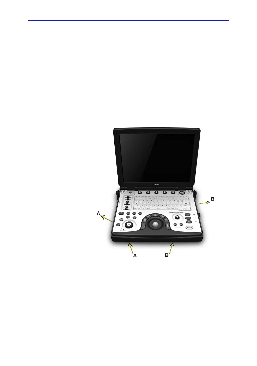
Air Flow Distribution
Figure 5-2. Air Flow Inside the System
The two air flow passes allow the scanner to be cooled down as
shown in the figure above.
• Path A (Bottom front > CPU Assy > Bottom left) for TMST &
CPU Assy cooling.
• Path B (Bottom front > PWA Assy > Bottom right) for PWA
cooling.

 Loading...


