4.23 Load Beams (B Model and Newer Beds)
Chapter 4: Removal, Replacement, and Adjustment Procedures
CareAssist® and CareAssist® ES Bed Service Manual (MAN330 REV 4) Page 4 - 73
4
4.23 Load Beams (B Model and Newer Beds)
Tools required: 13 mm socket
Ratchet
(2) Jack stands
T15 Torx®
1
screwdriver
Wire cutters
Antistatic strap
String, 10' (305 cm)
The load cell bracket assembly must be changed as an assembly. The
individual load cells are not replaceable.
Removal
1. Set the brakes.
2. Remove the headboard.
3. Raise the head section to the full up position.
4. For foot end load beams, do as follows, otherwise go to step 5:
a. Remove the foot and seat sections of the sleep deck.
b. Remove the central channel cover.
c. Mark the location of the cable ties and load cell cables attach to the bed.
Do not work under an unsupported load. Install appropriate supports.
Failure to do so could cause personal injury or equipment damage.
5. Place the jack stands under the articulating frame near the load cells being
replaced.
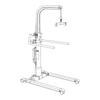
6. Remove the two screws (A) and washers (B) that attach the column cover
(C) to the column (D) (see figure 4-32 on page 4-74).
7. Remove the column cover (C).
1. Torx® is a registered trademark of Acument Intellectual Properties, LLC.

 Loading...