Mechanical System
Chapter 3: Theory of Operation
CareAssist® and CareAssist® ES Bed Service Manual (MAN330 REV 4) Page 3 - 3
3
unit travel up or down 15.7" (400 mm). Upper and lower end of travel (EOT)
switches that are backed up to make sure of electrical security. The system
does not require any special maintenance during its designed period of use.
However, the columns can be replaced in the event of a failure, but should
never be dismantled or repaired except by Hill-Rom personnel.
Casters
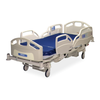
The bed has four casters: three brake and one brake/steer. Each caster has a 30°
inclination activation mechanism and three positions:
• Brake caster—Brake/Neutral/Neutral
• Steer caster—Brake/Neutral/Steer
The brake/steer caster is located on the left side, foot end. Antistatic brake
casters are standard for the remaining caster positions. They are identified by a
yellow dot on the tire.
Braking
The braking system comprises four brake casters that are controlled by the
brake/steer bar. The bar consists of two hexagonal bars with a connecting bar
situated in the right-hand box-section of the lower frame. The brake/steer bar is
directly mounted on the foot end hexagonal bar of the bed.
Steering
The left foot end caster is the steering caster. It is controlled by the brake/steer
bar.
Head and Footboards
The headboard and footboard feature an extruded/blow-moulded plastic
structure with chrome-plated steel clasps for assembly and decorative
laminated panels. The headboard and footboard are interchangeable and can be
used as a CPR backboard.
 Loading...
