Electrical System (A Model Beds)
Chapter 3: Theory of Operation
CareAssist® and CareAssist® ES Bed Service Manual (MAN330 REV 4) Page 3 - 5
3
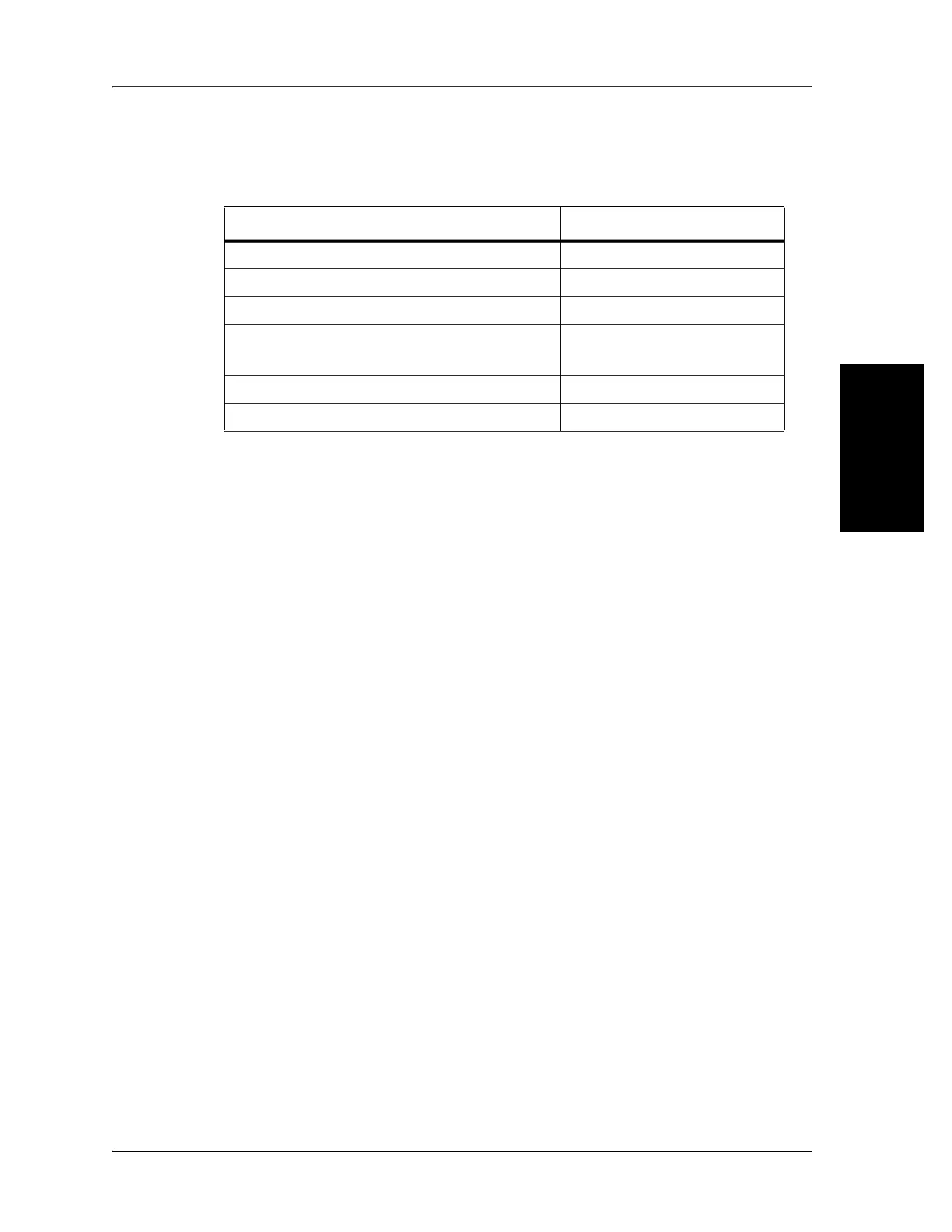
Power Supply Unit Characteristics
Table 3-2. Power Supply Unit Characteristics
The power supply unit is composed of the following components:
• Power stage
• Functions controlled by relays and transistors
• Battery charging circuit
• Control logic and specific functions
The functions are activated after electronically unlocking each of them by
using one of the following:
• Patient pendant
• Caregiver controls
Power Stage
The power stage is composed of a 120 V AC input transformer, protected at the
input by 2 antisurge fuses of 2.2 A and an internal thermal cutout that cannot
be reset. There is one non-fused secondary for the main control board and 1
fused secondary for the rest of the circuitry both followed at the outputs by
bridge rectifiers and filter capacitors. The value of this antisurge fuse is 1 A.
The non-fused secondary, through the bridge rectifier and filter capacitor,
produces an output voltage VDC1 which is approximately 24 V DC and
unregulated. The fused secondary produces a soft regulated 12 V DC for use in
the SideCom® Communication System P.C. board and Bed Exit System. The
available power enables several functions to be controlled simultaneously.
Description Specification
Input characteristics (see table 3-1 on page 3-4)
Fuse rating on primary 2.2 Slo-Blo®
a
a. Slo-Blo® is a registered trademark of LittleFuse, Inc.
Maximum power load 360 VA
Output voltage 18 to 40 V AC rectified,
filtered
Output power 360 VA
Continuos operation at 10 VA

 Loading...