IDS X-Series Training v2.7
9.2. Wireless Expander DIP switch operation
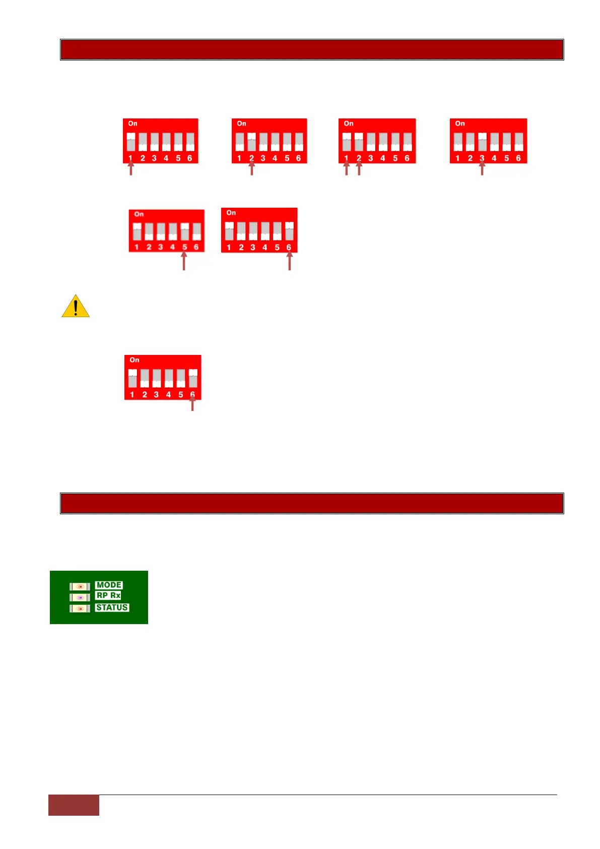
The dipswitch is used to set the device ID on the X-Series bus. This is done in binary the same as was done
for the wired expander save for one difference. That these expanders each cater for 16 zones and not 8 like
the wired expander.
Zones 1 – 16 Zones 17 – 32 Zones 33 – 48 Zones 49 - 64
Dip 1 Dip 2 Dip 1&2 Dip 3
Xwave Output configuration
PGM 1= RF Jam PGM 2 = Supervision Loss
Note: When dip switch 5 and 6 are:
OFF the outputs are then programmable.
ON the outputs are by default set to output 1 RF jam and output 2 supervision loss
Xwave
2
Remote Panic configuration
Put dipswitch 6 up to disable the 3 second any button panic
Default
If all dip-switches are ON during power-up then the unit will default, and delete all learnt wireless detector
serial numbers on the receiver. Please power down after, set appropriate ID and power up to resume normal
operation.
9.3. Wireless Expander LED Operation
Xwave LEDs
There are 3 LEDs on the Xwave board marked:
STATUS: indicates whether it’s connected to the X-Series alarm panel properly. If
the receiver notices X-Series communication then it will stay ON.
RF RX: indicates when the receiver receives a message from a learnt detector.
MODE: indicates current operating errors. If the LED is ON continuously then there
are no errors. If there are errors it will start pulsing the error number. These
error pulses will be separated by a 1sec pause with the LED OFF.
Xwave pulse error number:
1. Wireless receiver module not responding
2. No activity on the X-Series serial bus
3. No X-Series messages detected
4. No messages for this peripheral detected from X-Series
5. Not used
6. Expander not yet registered on the X-Series
7. Expander tamper violated
8. Unsupported DIP address configured
 Loading...