IDS X-Series Training v2.7
3. Panel Status LED
The status LED indicates the condition of the operating system.
Off = Not running
Flashing once a second = Normal operation
Flashing fast = Alarm Panel System fault
4. Serial Output
The serial connection on the X-Series alarm panel (Version 2.10 and up) can communicate with any device
that has the IDS Serial Protocol incorporated into it.
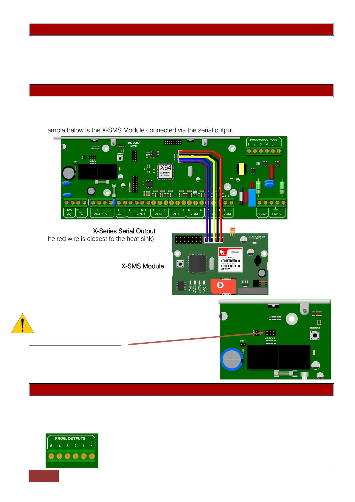
The example below is the X-SMS Module connected via the serial output:
X-Series Serial Output
(Note the red wire is closest to the heat sink)
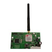
X-SMS Module
NOTE: As from X-Series v2.50 setting J1 is not required,
however in previous X-Series versions it’s used to set serial
mode to reporting or download (IDSwift2)
X-Series panel v2.00 - v2.41 only
J1 Closed to enable serial reporting.
J1 Open to allow IDSwift2 connection.
5. Programmable Outputs
Five positively triggered outputs that can supply 80mA of current.
By default: Output 1 will pulse if a panic or a duress is triggered
Output 2 will pulse if a burglary condition is triggered
Output 3 will latch on when the system is away armed
Output 4 will pulse if a fire condition is triggered
Output 5 will pulse if a medical condition is triggered
 Loading...