- 17 -
1 Servo System Selection
1
1.3.5 Motor Allowed Radial and Axial Loads
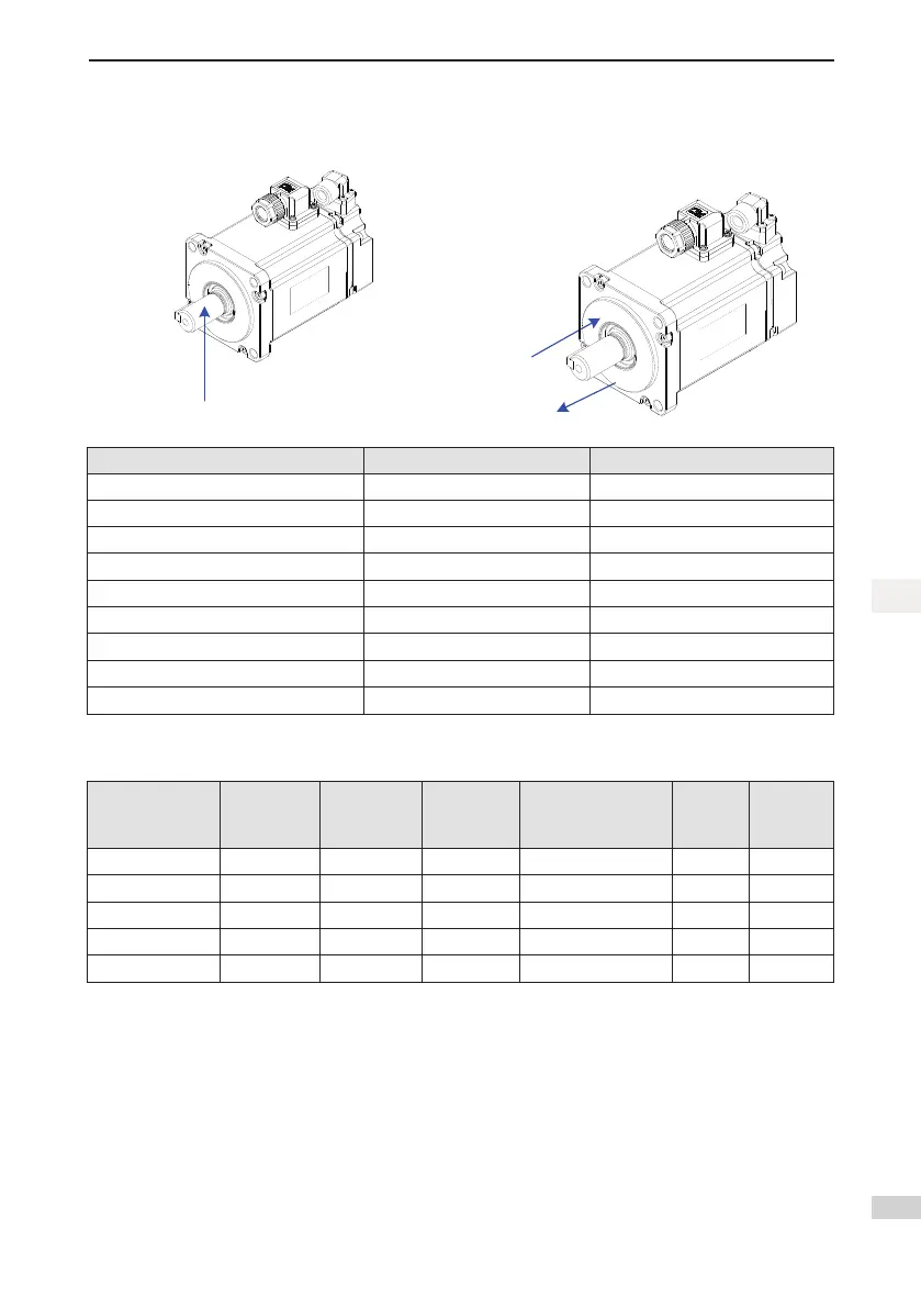
Figure 1-9 Motor radial and axial load diagram
Radial load on direction P
Axial load on direction A
Axial load on direction B
Motor Model Allowed Radial Load (N) Allowed Axial Load (N)
MS1H1-05B30CB-****Z-S 78 54
MS1H1-10B30CB-****Z-S 78 54
MS1H1-20B30CB-****Z-S 245 74
MS1H1-40B30CB-****Z-S 245 74
MS1H1-55B30CB-****Z-S 392 147
MS1H1-75B30CB-****Z-S 392 147
MS1H1-10C30CB-****Z-S 392 147
MS1H4-40B30CB-****Z-S 245 74
MS1H4-75B30CB-****Z-S 392 147
1.3.6 ElectricalSpecicationsoftheMotorBrake
Motor Model
Holding
Torque
(Nm)
Power Supply
Voltage
(V)±10%
Resistor
20
℃
,
(Ω)±10%
Power Supply Current
Range at 20
℃
(A)±10%
Brake
Release
Time (ms)
Brake
Apply Time
(ms)
MS1H1-05B/10B 0.32 DC 24 94.4 0.254 ≤20 ≤35
MS1H1-20B/40B 1.5 DC 24 75.79 0.3 ≤20 ≤35
MS1H1-75B 2.5 DC 24 72 0.333 ≤20 ≤60
MS1H4-40B 1.5 DC 24 75.79 0.3 ≤20 ≤50
MS1H4-75B 2.5 DC 24 72 0.333 ≤20 ≤60
Thebrakemustnotsharethepowersupplywithotherelectricaldevices.Thisistopreventamalfunctionof
thebrakeduetoadropinthevoltageorcurrentwhenotherelectricaldevicesworkintandem.
Cables of 0.5 mm2 and above are recommended.

 Loading...


