- 44 -
3 Wiring
3
3.4 Wiring of Encoder Cables
3.4.1 Connection of Series Incremental Encoder
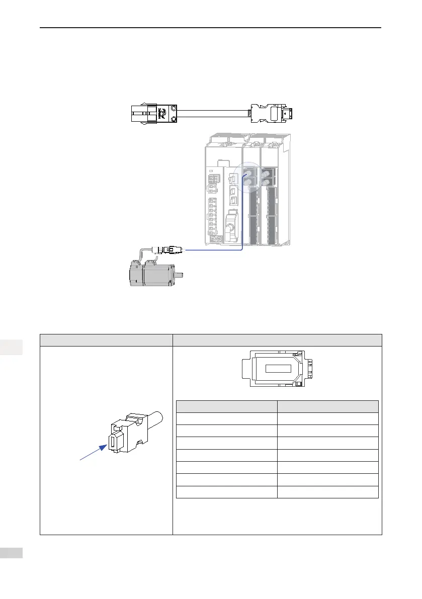
Figure 3-9 Example of connecting encoder signal cables
The encoder cable colors are subject to the actual cables. The cable colors mentioned in the guide are colors
of all Inovance cables.
Table 3-7 Connectors of SV820N series 20-bit encoder cables on servo drive side
Connector Appearance Terminal Pin Layout
Visual-in
through this
terminal
Pin No. Signal
1 +5V
2 0V
3 Reserved
4 Reserved
5 PS+
6 PS-
Housing PE
Recommended:
Connectorsatcableside:Sunchu,IEEE1394(6-pin,soldertype,
provided with a casing)

 Loading...


