- 42 -
3 Wiring
3
3.3 Wiring of Power Cables Between the Servo Drive and Servo Motor
3.3.1 WiringoftheMotorPowerCableswiththeBrake
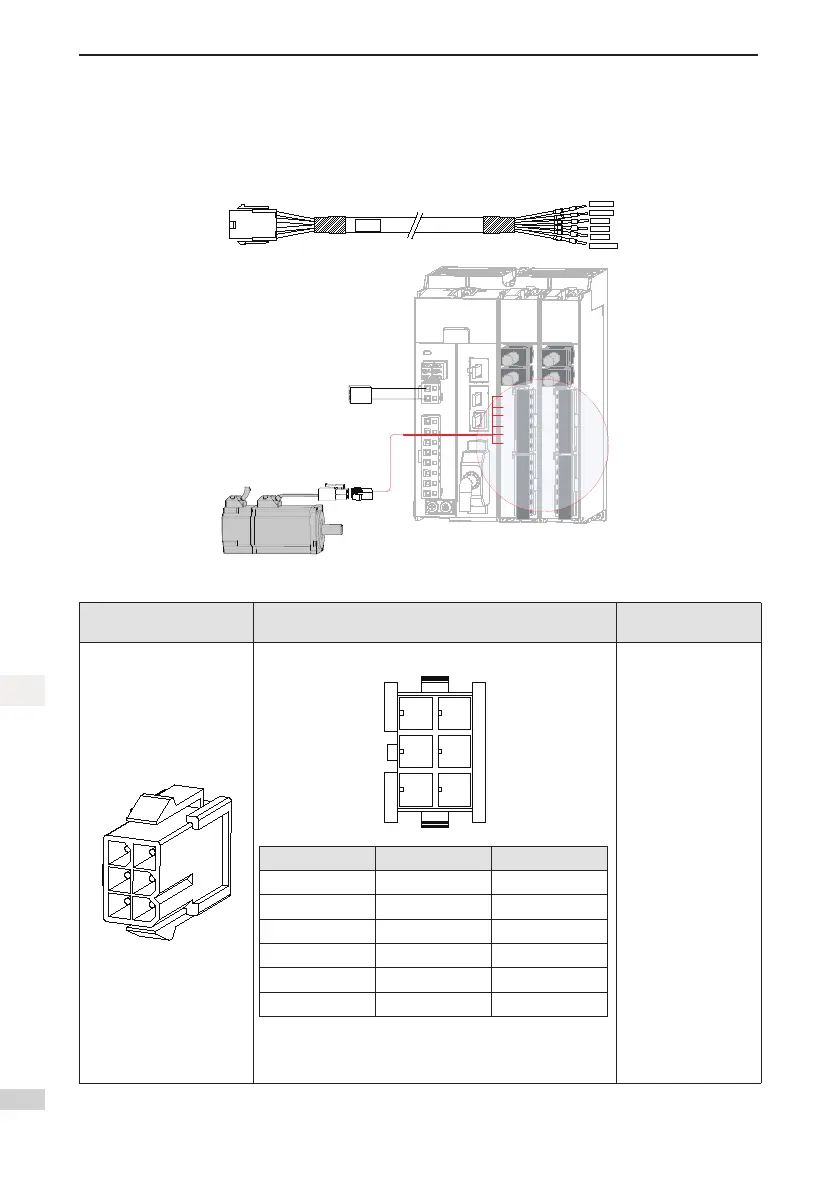
Figure 3-7 Example of connecting the servo drive and servo motor
BR+
BR-
PE
U
V
W
Power supply
(24 V DC)
V
W
PE
U
BK
-
BK+
Yellow/Green-PE
Red-W
Black-V
White
-U
Blue-BK-
Brown-BK+
Table 3-6 Connectors of power cables on the servo motor side
Connector Appearance Terminal Pin Layout
Frame Size of
Adaptable Motor
Black6-pinconnector
Pin No. Signal Color
1 U White
2 V Black
4 W Red
5 PE Yellow/Green
3 BR+ Brown
6 BR- Blue
Recommended:
● Plastichousing:MOLEX-50361736
● Terminal:MOLEX-39000061
40 (Z series)
60 (Z series)
80 (Z series)

 Loading...


