- 35 -
3 Wiring
3
3.1 Servo Drive Main Circuit Wiring
3.1.1 Main Circuit Terminals
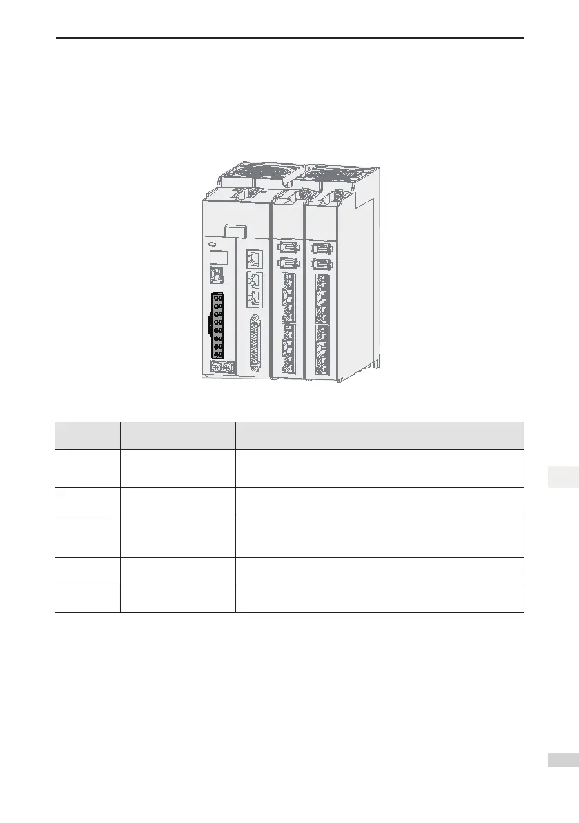
Main circuit input terminals of the SV820N multi-axis servo drive
Figure 3-2 Main circuit terminal arrangement
Table 3-1 Names and functions of the main circuit terminals of the SV820N servo drive
Terminal
Symbol
Terminal Name Terminal Function
L1, L2, L3
Main circuit power input
terminals
Main circuit single-phase/three-phase 220 V power input. Terminals L1
and L2 are for single-phase power input, and terminals L1, L2 and L3
are for three-phase power input.
L1C, L2C
Control power input
terminals
Control circuit 220 V AC power input.
P, C
Terminals for connecting
external bleeder resistor
Whenlarge-inertialoadneedsbrakingforemergencystop,connectan
external bleeder resistor between P and C.
The external bleeder resistor needs to be purchased additionally.
P, N Common DC bus terminal
They are used for common DC bus connection when multiple servo
drives are under parallel control.
PE Ground
Two grounding terminals of the servo drive are respectively connected
to those of the power supply and the servo motor.

 Loading...


