- 36 -
3 Wiring
3
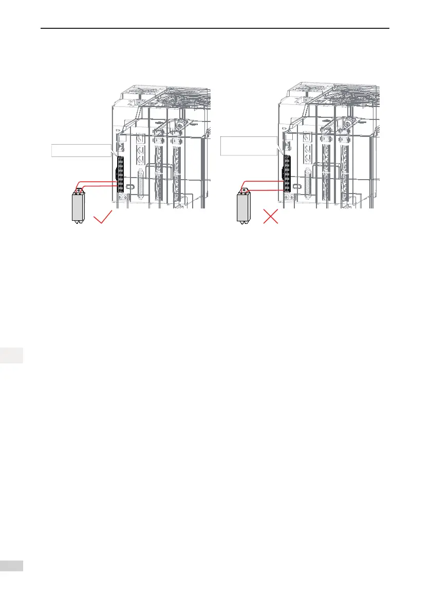
3.1.2 Examples of Bleeder Resistor Incorrect Wiring
Figure 3-3 Connection diagram of the external bleeder resistor
C
C
P
P
L
L
3
3
L
L
2
2
L
L
1
1
L
L
2
2
C
C
L
L
1
1
C
C
N
N
PE
PE
Braking resistor connected
between P and C
C
C
P
P
L
L
3
3
L
L
2
2
L
L
1
1
L
L
2
2
C
C
L
L
1
1
C
C
N
N
PE
PE
The external
regenerative resistor
terminals are not connected
Observethefollowingprecautionswhenconnectingtheexternalbleederresistor:
1. Do not directly connect the external bleeder resistor to the bus’s positive pole (P) and negative pole (N).
Failuretocomplywillleadtodamageoftheservodriveorare.
2. Do not select any resistor lower than the minimum allowed resistance value. Failure to comply will result
in Er.201 warning or damage to the drive.
3. Makesurethat2002-1Ah,2002-1Bhand2002-1Choftheexternalbleederresistorareaccuratelyset
before using the servo drive.
4. Install the external bleeder resistor on incombustible matters (such as a metal).

 Loading...


