- 40 -
3 Wiring
3
3.1.5 Precautions for Main Circuit Wiring
1. Do not connect the input power cables to the output terminals U, V and W. Failure to comply will cause
damage to the servo drive.
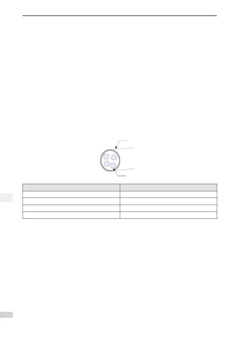
2. Whencablesarebundledinaduct,takecurrentreductionintoconsiderationsincetheheatdissipation
condition deteriorates.
3. When temperature inside the cabinet is higher than the temperature limit of the cables, select those
cableswithahighertemperaturelimit.Teoncablesarerecommended.Asthesurfaceofgeneralca-
blesiseasytohardenandbreak,takethermalinsulationmeasuresforcableslaidinalowtemperature
environment.
4. The bending radius of a cable shall exceed 10 times that of its outer diameter to prevent the internal wire
corefrombreakingduetolongtimebending.
5. Select and use cables with rated voltage of 600 V AC (and above) and temperature of 75℃ (and above).
Under the ambient temperature of 30℃ and normal heat dissipation conditions, the allowable current
density of the cables shall not exceed 8 A/mm
2
when the total current is below 50 A, or 5 A/mm
2
when the
total current is above 50 A. This value can be adjusted when the ambient temperature is high or when the
cables are bundled. The allowable current density (A/mm
2
)iscalculatedasfollow:
Allowablecurrentdensity=8×reductioncoefcientofcurrent-carryingconductordensity×
currentcorrectioncoefcient
Number of Cables in the Same Duct CurrentReductionCoefcient
Less than 3 cores 0.7
4 cores 0.63
5–6 cores 0.56
7–15 cores 0.49
6. The bleeder resistor cannot be connected between DC bus terminals P and C. Failure to comply may
causeare.
7. Do not bundle power cables and signal cables together or run them through the same duct. Power and
signal cables shall be separated by at least 30 cm to prevent interference.
8. High voltage may still remain in the servo drive when the power supply is cut off. Do not touch the power
terminals within 5 minutes after powering off.
9. Do not frequently turn ON and OFF the power supply. If the power supply needs to be switched on or off
repeatedly,makesurethatthetimeintervalisatleastoneminute.Astheservodrivecontainsacapac-
itorinthepowersupply,alargechargingcurrentowsfor0.2secondswhenthepowersupplyisturned
OFF. Frequently turning ON and OFF the power supply will deteriorate performance of the main circuit
components inside the servo drive.
10. Use a grounding cable with the same cross-sectional area as the main circuit cable. If the cross-sectional
area of the main circuit cable is less than 1.6 mm
2
, use a grounding cable with a cross-sectional area
of 2.0 mm
2
.
11. Ground the servo drive to the earth reliably.
12. Donotpowerontheservodriveifanycablesbecomeloose.Otherwise,aremayoccur.

 Loading...


