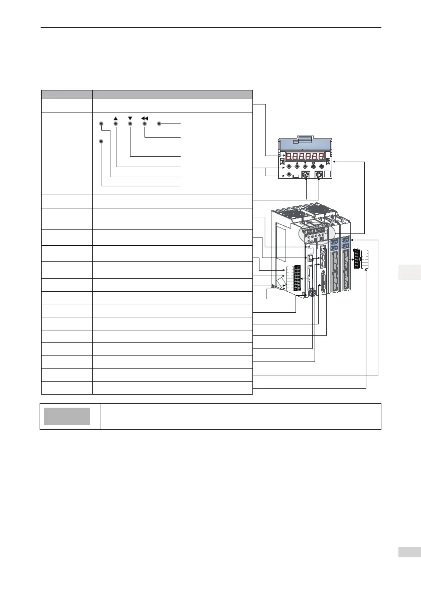
MODE
SET
SEL
IDH IDL
Name
Purpose
Key operator
Select the specific Axis
number with the key
LED display
The 6-digital 7-segment LED display is used to show servo system’s running state and
parameter setting
MODE
SET
SEL
Go to the lower-level menu
Execute commands such as
storing parameter setting value
Change the value of the blinking
digit for the LED
View the high digits of the number
consisting of more than 5 digits
Decrease the value of the blinking
digit for the LED
Increase the value of the blinking
digit for the LED
Switch between all modes
Return to the upper-level menu
IDH, IDL
Setting the node address for
the equipment
BR+
BR-
PE
W
V
U
Reserved
CHARGE light
Bus voltage indicator
Used to indicate the bus capacitor with charges. When the indicator turns on,
charges possibly still exist in the internal capacitor of the servo unit, even if the power
supply of the main circuit is OFF. Therefore, do not touch the power terminals to
avoid electrical shock.
L1C
L2C
L1
P
L3
L2
C
N
L1, L2, L3
Main circuit power input
terminals
L1C, L2C
Control circuit power input
terminals
P, N
DC bus terminals
PE
Grounding terminal
CN7
24 V brake power input
CN1
Control terminal
CN3
Ethernet connection terminal
CN4
EtherCAT output terminal
CN5
EtherCAT input terminal
ErherCAT network interface, CN5 (IN) connecting to master station or previous slave station
X1, X2
Terminals used to
connect the encoder
X3, X4
Main circuit signal terminals
for the drive unit
Main circuit single-phase and three-phase 220 V power input.
Terminals L1 and L2 are for single-phase power input, and terminals L1, L2 and L3 are for
three-phase power input.
Control circuit 220 V AC power input.
P, N:They are used for common DC bus connection when multiple servo drives are under
parallel control.
Two grounding terminals of the servo drive are respectively connected to those of the power
supply and the servo motor.
Port for digital input/output signal
ErherCAT network interface, CN4 (OUT) connecting to next slave station
Ethernet connector port
P, C
External bleeder resistor
connection terminals
External bleeder resistor is connectedbetween P and C when the servo systemis under
feedbackBraking mode. Externalis under feedbackresistor needs to be purchased additionally.
Connect with the motor encoder terminals
BR+, BR-: Coils of the motor with brake
U, V, W: Connect the phases U, V and W of servo motor
24 V brake power input (you must use this port to input 24 V
power in order to use the brake power)
Themotorwithbrakemustbesuppliedwith24VpowerviatheCN7terminalontheservo
drive.ThepowermustbeoutputtothewiringterminalofthebrakeviaBR+andBR-.

 Loading...


