- 33 -
3 Wiring
3
Chapter 3 Wiring
DANGER
● Wiring must be performed by professional technicians.
● Toavoidtheelectricshock,leavetheservodriveformorethanveminutesafterpowered
off,waituntilthepowerindicatorturnsoffcompletely,andcheckthevoltagebetweenPand
N by using a multimeter. Then, disassemble or assemble the drive.
● Perform wiring after the servo drive and motor are installed properly. Failure to comply will
resultinelectricshock.
● Do not damage the cables, lay them under large tension or pressure, or hang them. Failure
tocomplymayresultinelectricshock.
● Insulatethepowerterminalconnectorstopreventelectricshock.
● Thespecicationsandinstallationmethodofexternalcablesmustcomplywiththe
applicable local regulations.
● The cables must be copper and the grounding cable must be the yellow-green one as
shown in Table 3-2.
● The entire system must be grounded.
● Carry out wiring correctly. Failure to comply will result in abnormal action of the servo motor
and personal injury.
● Donotmistaketheterminalconnection.Failuretocomplymayresultindamagetothe
terminals.
● Makesuretoconnecttheelectromagneticcontactorbetweenthepowersupplyandmain
circuit of the drive (L1 and L2 for single-phase, and R, S and T for three-phase) to form
a structure that can cut off the power supply at the power supply side of servo drive. If
noelectromagneticcontactorisconnected,aremayoccurwhenafaultoccursand
continuouslargecurrentowsthroughthedrive.
● UsetheALM(faultsignal)tocutoffthemaincircuitpowersupply.Ifthebrakingtransistor
fails,thebleederresistormayoverheat,causingare.
● Beforepoweringon,checkthevoltagespecicationsofthedrive.NEVERconnectthe380
V power supply to the 220 V drive. Failure to comply will damage the drive.
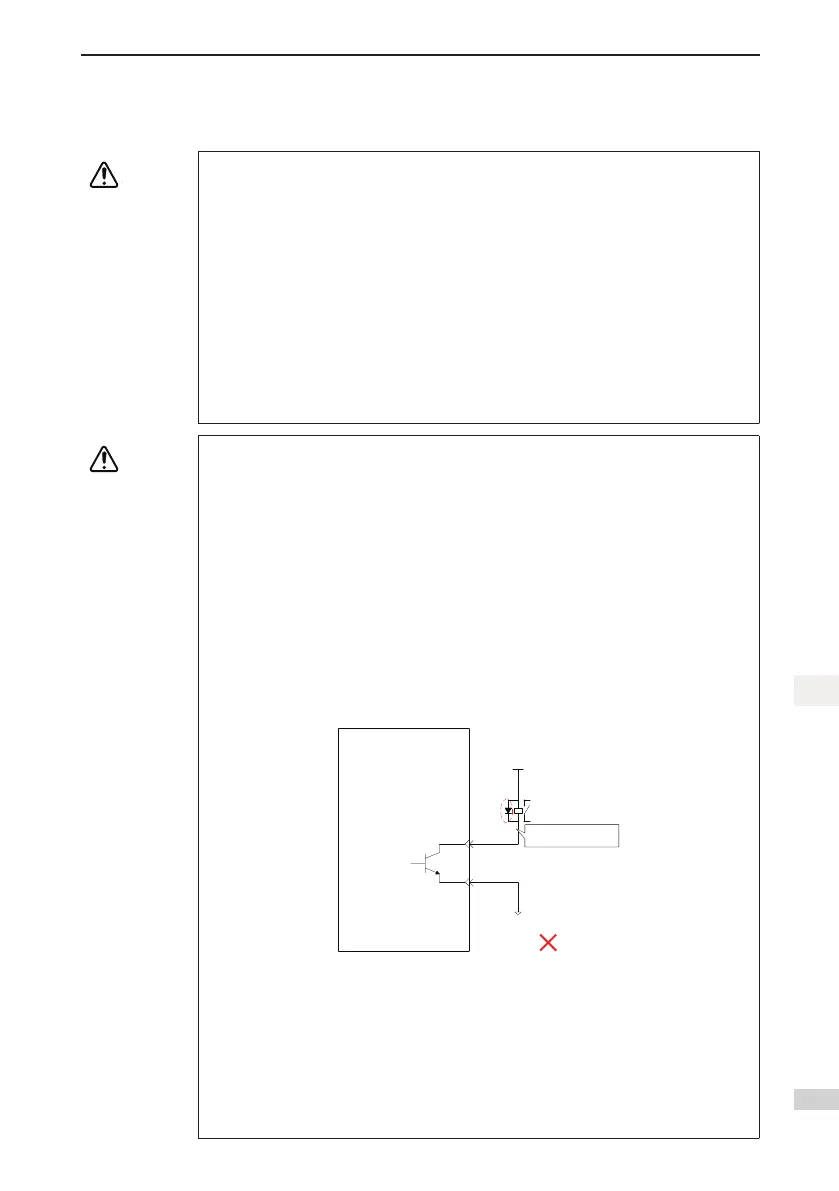
● Donotreversethedirectionsoftheywheeldiode.Failuretocomplywilldamagethedrive
and affect signal output.
Servo Drive
External 5−24 V DC
DO1-
DO1+
6
7
Relay
External 0 V
Flywheel diode
polarity error
● Use a noise lter to reduce electromagnetic interference on electronic devices
around the drive.
● Forthe power supplyandthe maincircuit connection,makesure thatthe main
circuit power supply is cut off and the servo ON state changes to the OFF state
after the alarm signal is detected.
● Connect the U, V, W cables of the drive to the U, V, W terminals of the motor di-
rectly. Do not connect an electromagnetic contactor. Failure to comply may result
in abnormalities and faults.

 Loading...


