Goodrive35 Series Closed-loop Vector Control VFD Fault tracking
200
Chapter 8 Fault tracking
8.1 What this chapter contains
This chapter tells how to reset faults and view fault history. It also lists all alarm and fault messages
including the possible cause and corrective actions.
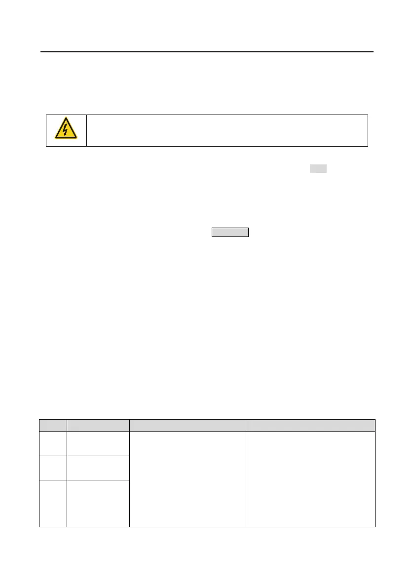
Only qualified electricians are allowed to maintain the VFD. Read the safety
instructions in chapter Safety precautions before working on the VFD.
8.2 Alarm and fault indications
Fault is indicated by LEDs. See Chapter 5 "Keypad operation procedures". When TRIP light is on, an
alarm or fault message on the panel display indicates abnormal VFD state. Using the information
given in this chapter, most alarm and fault cause can be identified and corrected. If not, contact the
INVT office.
8.3 How to reset
The VFD can be reset by pressing the keypad key STOP/RST, through digital input, or by switching
the power light. When the fault has been removed, the motor can be restarted.
8.4 Fault history
Function codes P07.27–P07.32 store 6 recent faults. Function codes P07.33–P07.40, P07.41–P7.48,
P07.49–P07.56 show drive operation data at the time the latest 3 faults occurred.
8.5 Fault instruction and solution
Do as the following after the VFD fault:
1. Check to ensure there is nothing wrong with the keypad. If not, contact the local INVT office.
2. If there is nothing wrong, please check P07 and ensure the corresponding recorded fault
parameters to confirm the real state when the current fault occurs by all parameters.
3. See the following table for detailed solution and check the corresponding abnormal state.
4. Eliminate the fault and ask for relative help.
5. Check to eliminate the fault and carry out fault reset to run the VFD.
8.5.1 VFD faults and solutions
Inverter unit U
phase protection
The acceleration is too fast
There is damage to the internal
to IGBT of the phase
Misoperation is caused by
interference.
The connection of the driving
wires is not good
Short-to-ground occurs.
Increase acceleration time
Change the power unit
Check the driving wires
Check if there is strong interference
to the external equipment
Inverter unit V
phase protection
Inverter unit W
phase protection

 Loading...