Goodrive35 Series Closed-loop Vector Control VFD Keypad operation procedures
41
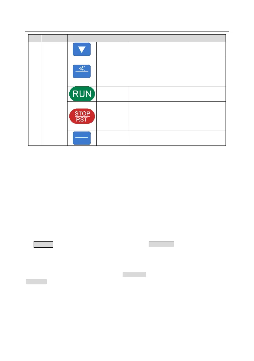
Decrease data or function code progressively
Move right to select the displaying parameter
circularly in stopping and running mode.
Select the parameter modifying digit during the
parameter modification
This key is used to operate on the VFD in key
operation mode
This key is used to stop in running state and it
is limited by function code P07.04
This key is used to reset all control modes in
the fault alarm state
The function of this key is confirmed by
function code P07.02.
5.3 Keypad displaying
The keypad displaying state of Goodrive35 series VFDs is divided into stopping state parameter,
running state parameter, function code parameter editing state and fault alarm state and so on.
5.3.1 Displayed state of stopping parameter
When the VFD is in the stopping state, the keypad will display stopping parameters which is shown in
Figure 5-2.
In the stopping state, various kinds of parameters can be displayed. Select the parameters to be
displayed or not by P07.07. See the instructions of P07.07 for the detailed definition of each bit.
In the stopping state, there are 14 stopping parameters can be selected to be displayed or not. They
are: set frequency, bus voltage, input terminals state, output terminals state, PID given value, PID
feedback value, torque set value, AI1, AI2, AI3, HDI, PLC and the current stage of multi-step speeds,
pulse counting value, length value. P07.07 can select the parameter to be displayed or not by bit
and》/SHIFT can shift the parameters form left to right, QUICK/JOG (P07.02=2) can shift the
parameters form right to left.
5.3.2 Displayed state of running parameters
After the VFD receives valid running commands, the VFD will enter into the running state and the
keypad will display the running parameters. RUN/TUNE LED on the keypad is on, while the
FWD/REV is determined by the current running direction which is shown as Figure 5-2.
In the running state, there are 24 parameters can be selected to be displayed or not. They are:
running frequency, set frequency, bus voltage, output voltage, output torque, PID given value, PID
feedback value, input terminals state, output terminals state, torque set value, length value, PLC and
the current stage of multi-step speeds, pulse counting value, AI1, AI2, AI3, HDI, percentage of motor
overload, percentage of VFD overload, ramp given value, linear speed, AC input current. P07.05 and

 Loading...