Goodrive35 Series Closed-loop Vector Control VFD Installation guide
35
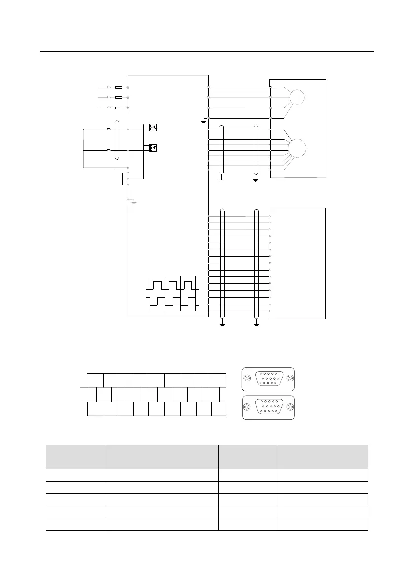
4.4.5.4 The wiring diagram
+24V
PE
COM
S8
S1
PW
A1-
A1+
GND
+5V
B1+
B1-
Z1+
Z1-
R
S
T
U
V
W
U
V
W
M
3~
Encoder
ZO-
CME
COM
S7
CNC OR PLC
Y
.
.
.
.
.
.
.
.
.
.
.
.
COM
S8
A2+
A2-
B2+
AO-
BO+
BO-
ZO+
AO+
B2-
COM
pulse A
pulse B
PE
PE
Ground one terminal
C-
A-
B+
B-
C+
A+
ALM+
ALM-
SON
SCR
CW+
CW-
CCW+
CCW-
SCOM
Encoder Feedback
PE
PE
Ground one terminal
4.4.6 S1 terminal (EC-PG302-05) instruction
4.4.6.1 Sin/cos terminal layout
S1 S2 S3 S4 HDI AI1 AI3 GND +10V
S5 S6 S7 S8 HDO COM AO1 AO2 GND
+24V PW COM COM CME Y1 485+ 485- PE
1
6
11
15
5
10
15
5
10
1
6
11
Lower layer: sin/cos
PG interface
Upper layer:
Reference and output
4.4.6.2 DB15 interface instruction
Pulse reference and output
interface signal
Sin/cos encoder
interface signal

 Loading...