Goodrive35 Series Closed-loop Vector Control VFD Communication protocol
219
10.3.2 RTU mode
10.3.2.1 RTU communication frame format
If the controller is set to communicate by RTU mode in Modbus network every 8bit byte in the
message includes two 4Bit hex characters. Compared with ACSII mode, this mode can send more
data at the same baud rate.
Code system
1 start bit
7 or 8 digital bit, the minimum valid bit can be sent firstly. Every 8 bit frame includes two hex
characters (0...9, A...F)
1 even/odd check bit. If there is no checkout, the even/odd check bit is inexistent.
1 end bit (with checkout), 2 bit (no checkout)
Error detection field
CRC
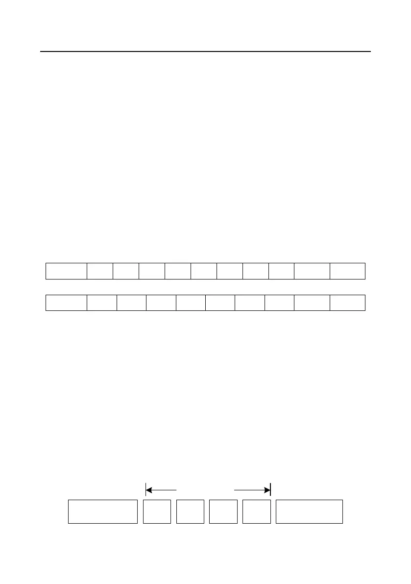
The data format is illustrated as below:
11-bit character frame (BIT1–BIT8 are the data bits)
10-bit character frame (BIT1–BIT7 are the data bits)
In a character frame, only the data bits carry information. The start bit, check bit, and end bit are used
to facilitate the transmission of the data bits to the destination device. In practical applications, you
must set the data bits, parity check bits, and end bits consistently.
In RTU mode, the transmission of a new frame always starts from an idle time (the transmission time
of 3.5 bytes). On a network where the transmission rate is calculated based on the baud rate, the
transmission time of 3.5 bytes can be easily obtained. After the idle time ends, the data domains are
transmitted in the following sequence: slave address, operation command code, data, and CRC
check character. Each byte transmitted in each domain includes 2 hexadecimal characters (0–9, A–F).
The network devices always monitor the communication bus. After receiving the first domain (address
information), each network device identifies the byte. After the last byte is transmitted, a similar
transmission interval (the transmission time of 3.5 bytes) is used to indicate that the transmission of
the frame ends. Then, the transmission of a new frame starts.
RTU data frame format
Modbus packet
Start with an idle time (at
least the transmission
time of 3.5 bytes)
Slave
address
Function
code
Data Check
End with an idle time (at
least the transmission
time of 3.5 bytes)