Goodrive35 Series Closed-loop Vector Control VFD Installation guide
31
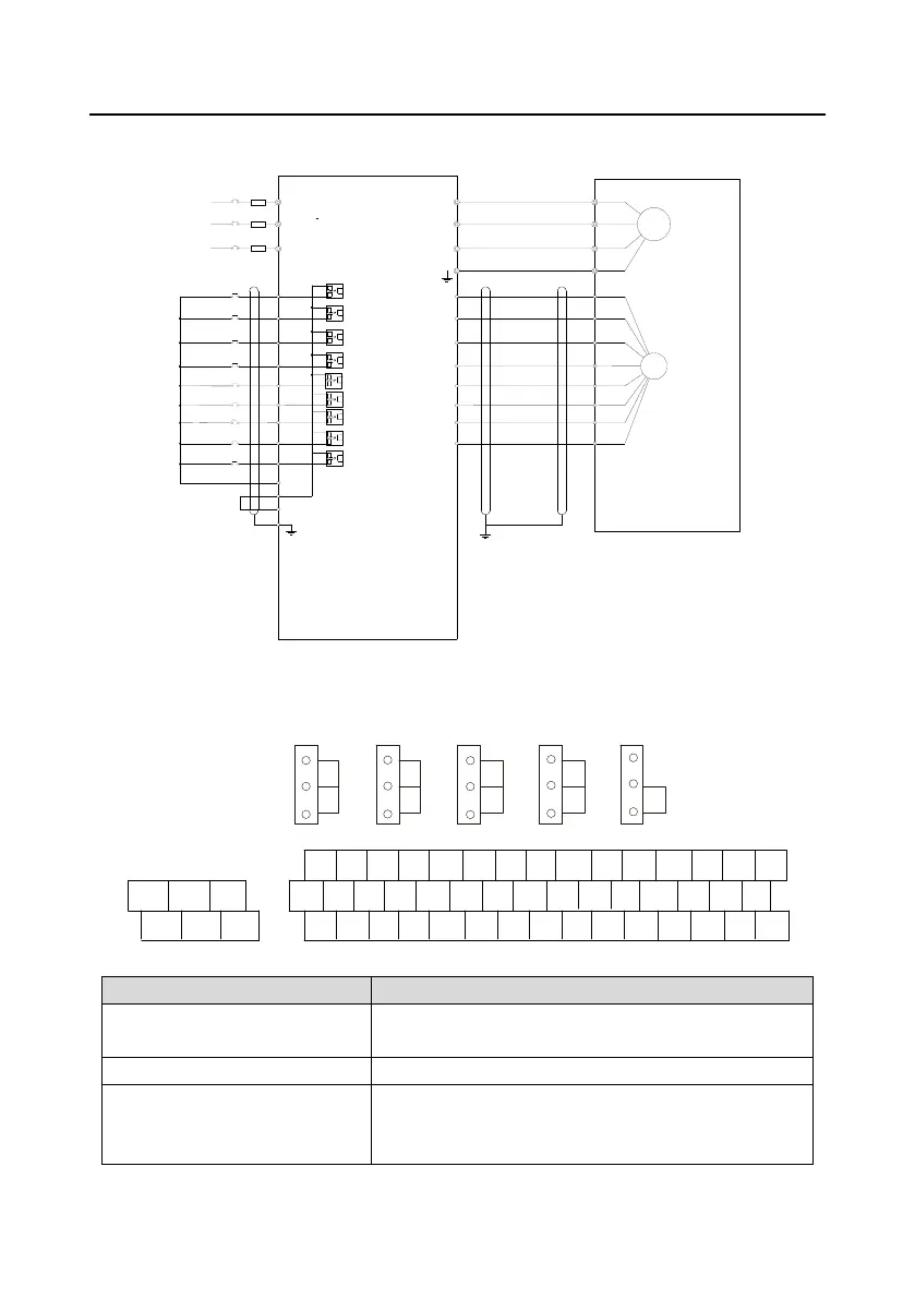
4.4.2.3 Wiring diagram
+24V
PE
COM
S4
S3
S2
S1
HD1
PW
S5
S6
S7
S8
A-
A+
COM1
24V
B+
B-
Z+
Z-
R
S
T
U
V
W
U
V
W
M
3~
PG
High-speed pulse input
and open collector input
Spindle scaling selection
3
Spindle scaling selection
2
Spindle scaling selection
1
Spindle positioning
disabled
Spindle zeroing
Fault reset
Spindle rotates backward
Spindle rotates forward
4.4.3 D1 terminal (EC-PG304-05) instruction and the wiring diagram
4.4.3.1 Terminal arrangement
V
AO1 AO2 AI
1
AI 2 485
I
V
I
V
I
V
I ON
J1 J2 J3 J4 J5
RO1A RO1B RO1C
RO2A RO2B RO2C
S1 S2 S3 S4 HDI A+ A- AI1 AI2 AI3 +10V SIN+ SIN- AO+ AO-
S5 S6 S7 S8 HDO B+ B- GND AO1 AO2 GND COS+ COS- BO+ BO-
+24V PW COM COM CME Y1 485+ 485- PE GND EXC+ EXC- ZO+ ZO- PE
4.4.3.2 Terminal instruction
Exciting signal of 10k Hz, and max. output current of 100
mA.
SIN+, SIN- , COS+ and COS-
Encoder differential signal input.
Pulse reference signal, default as 5 V input. External
current-limiting resistor is needed when the input voltage
is above 10 V.

 Loading...