EasyManua.ls Logo

INVT Goodrive35 Series User Manual

INVT Goodrive35 Series
298 pages
To Next Page IconTo Next Page
To Previous Page IconTo Previous Page
Page #233 background imageLoading...
Page #233 background image
Goodrive35 Series Closed-loop Vector Control VFD Communication protocol
226
LSB of data quantity
02H
Number of bytes
04H
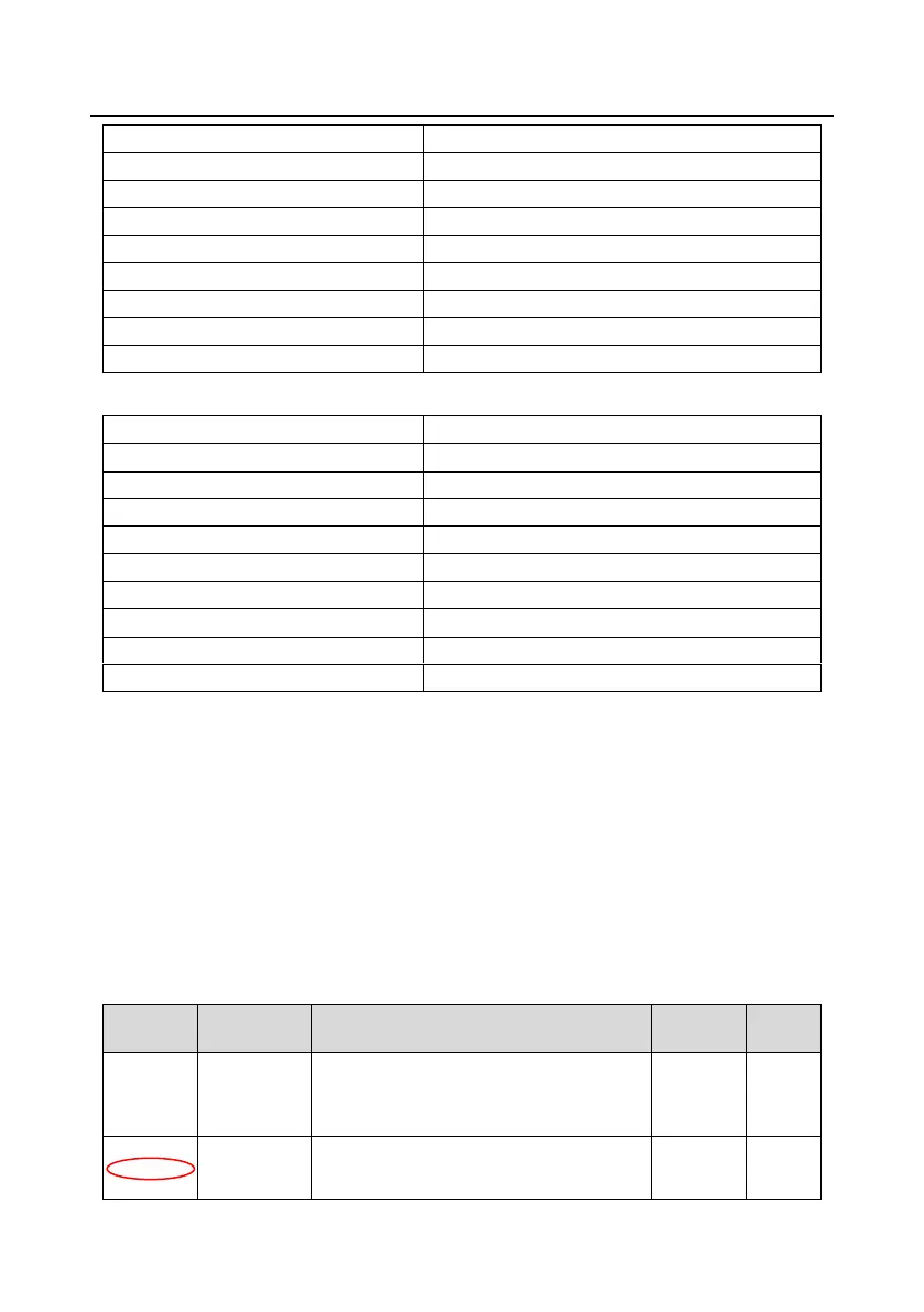
MSB of data to be written to 0004H
13H
LSB of data to be written to 0004H
88H
MSB of data to be written to 0005H
00H
LSB of data to be written to 0005H
32H
LSB of CRC
C5H
MSB of CRC
6EH
END
T1-T2-T3-T4 (transmission time of 3.5 bytes)
RTU slave response (transmitted by the VFD to the master)
START
T1-T2-T3-T4 (transmission time of 3.5 bytes)
ADDR
02H
CMD
10H
MSB of data writing address
00H
LSB of data writing address
04H
MSB of data quantity
00H
LSB of data quantity
02H
LSB of CRC
C5H
MSB of CRC
6EH
END
T1-T2-T3-T4 (transmission time of 3.5 bytes)
10.4.5 The definition of data address
This section describes the address definition of communication data. The addresses are used for
controlling the running, obtaining the state information, and setting related function parameters of the
VFD.
10.4.5.1 The rules of parameter address of the function codes
The address of a function code consists of two bytes, with the MSB on the left and LSB on the right.
The MSB ranges from 00 to ffH, and the LSB also ranges from 00 to ffH. The MSB is the hexadecimal
form of the group number before the dot mark, and LSB is that of the number behind the dot mark.
Take P05.06 as an example, the group number is 05, that is, the MSB of the parameter address is the
hexadecimal form of 05; and the number behind the dot mark is 06, that is, the LSB is the
hexadecimal form of 06. Therefore, the function code address is 0506H in the hexadecimal form. For
P10.01, the parameter address is 0A01H.
Function
code
Name
Detailed parameter description
Default
value
Modify
P10.00
Simple PLC
0: Stop after running once.
1: Run at the final value after running once.
2. Cycle running.
0
P10.01
Simple PLC
memory
selection
0: Power loss without memory
1: Power loss with memory
0

Table of Contents

Question and Answer IconNeed help?

Do you have a question about the INVT Goodrive35 Series and is the answer not in the manual?

INVT Goodrive35 Series Specifications

General IconGeneral
Protection LevelIP20
Power Range0.75kW ~ 630kW
Control ModeSVC
Overload Capacity150% for 60 seconds, 180% for 10 seconds
Braking UnitBuilt-in or external optional braking unit
Communication ProtocolModbus
Protection FeaturesOvervoltage, Undervoltage, Overcurrent, Overload, Overtemperature, Short Circuit, Phase Loss
Ambient Temperature-10°C to +50°C
HumidityLess than 95% RH (non-condensing)
AltitudeBelow 1000m (derating above 1000m)
Cooling MethodForced air cooling

Summary

Chapter 1 Safety precautions

1.4 Safety guidelines

General rules and precautions for operating the VFD safely.

Chapter 2 Quick start-up

2.5 Installation confirmation

Checks to perform after the VFD has been physically installed.

2.6 Basic commission

Essential commissioning steps to perform before the VFD is put into actual operation.

Chapter 3 Product overview

3.3 Product specification

Details the technical specifications of the VFD across various functions.

3.6 Rated values

Lists electrical and performance ratings for different VFD models.

Chapter 4 Installation guide

4.2 Mechanical installation

Covers environmental requirements and installation methods for the VFD.

4.3 Standard wiring

Details the wiring diagrams for the main and control circuits of the VFD.

4.4 Standard wiring (control circuit)

Explains the wiring for various control circuit terminals and interfaces.

4.5 Wiring protection

Guidance on protecting the VFD and cables from electrical issues.

Chapter 5 Keypad operation procedures

5.2 Keypad

Details the VFD's keypad for control, data reading, and parameter modification.

5.4 Keypad operation

Instructions on how to navigate menus and modify VFD function codes.

Chapter 6 Function parameters

6.2 Goodrive35 general series function parameters

Detailed explanation of the VFD's function parameter groups and codes.

Chapter 7 Basic operation instruction

7.2 First powering on

Steps for initial power-up, checks, and VFD initialization.

7.3 Vector control

Explains the principles and application of vector control for asynchronous motors.

7.5 Torque control

Covers the two control modes, torque and rotation speed control, and their implementation.

7.6 Parameters of the motor

Crucial motor parameters that need to be set for VFD operation and autotuning.

7.7 Start-up and stop control

Explains the different modes for starting and stopping the VFD.

7.8 Frequency setting

Describes various methods for setting the VFD's operating frequency.

Chapter 8 Fault tracking

8.3 How to reset

Methods for resetting VFD faults via keypad, digital input, or power cycling.

8.5 Fault instruction and solution

Steps to diagnose and resolve VFD faults, including tables of common faults.

8.6 Common fault analysis

Troubleshooting guides for common VFD issues like motor not working or vibration.

Chapter 9 Routine maintenance

9.2 Maintenance intervals

Lists recommended routine maintenance checks and their criteria.

Chapter 10 Communication protocol

10.4 RTU command code and communication data illustration

Explains RTU frame formats, command codes, and data structure for communication.

Related product manuals