Goodrive35 Series Closed-loop Vector Control VFD Installation guide
30
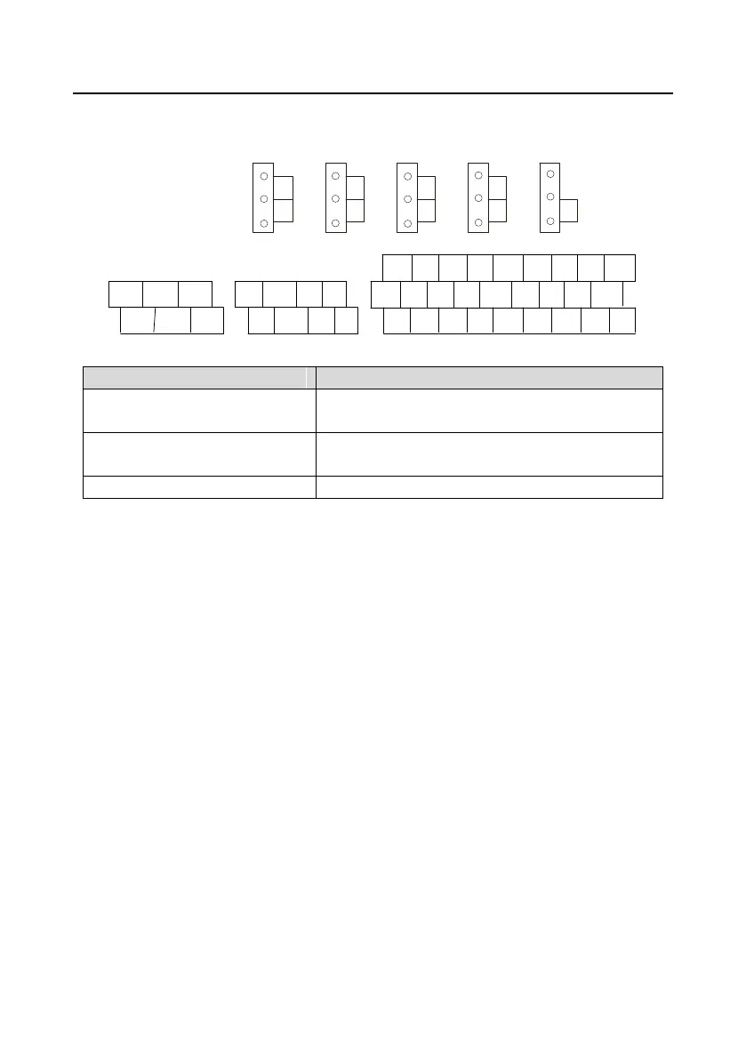
4.4.2 C1 terminal (EC-PG301-24) instruction and the wiring diagram
4.4.2.1 Terminal arrangement
V
AO1 AO2 AI
1
AI 2 485
I
V
I
V
I
V
I ON
J1 J2 J3 J4 J5
RO1A RO1B RO1C
RO2A RO2B RO2C
A+ A- B+ B-
+24V COM Z+ Z-
S1 S2 S3 S4 HDI AI1 AI2 AI3 +10V
S5 S6 S7 S8 HDO GND AO1 AO2 GND
+24V PW COM COM CME Y1 485+ 485- PE
4.4.2.2 Terminal instruction
Encoder power supply.
It can provide power supply of 24 V, 200 mA.
Support encoder signal differential, push-pull, and open
collector input.
Power supply ground of the encoder
Note: Refer to section 4.4.1 for detailed information of AO1, AO2, AI1, AI2, 485 and other terminals.

 Loading...