Goodrive35 Series Closed-loop Vector Control VFD Technical data
257
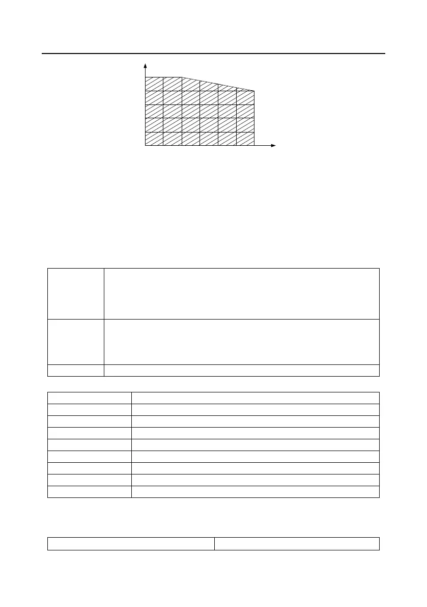
Derating coefficient (%)
100
80
60
40
20
0
1000 2000 3000
Altitude (m)
When the altitude exceeds 2000m, configure an isolation transformer on the input end of the VFD.
When the altitude exceeds 3000m but is lower than 5000m, contact us for technical consultation. Do
not use the VFD at an altitude higher than 5000m.
B.2.2.3 Carrier frequency derating
The power of Goodrive350 series VFDs varies according to carrier frequencies. The rated power of a
VFD is defined based on the carrier frequency set in factory. If the carrier frequency exceeds the
factory setting, the power of the VFD is derated by 10% for each increased 1 kHz.
B.3 Grid specifications
AC 3PH 380 V (-15%)–440 V (+10%)
AC 3PH 380 V (-10%)–550 V (+10%)
AC 3PH 520 V (-15%)–690 V (+10%)
According to the definition in IEC 60439-1, the maximum allowable short-circuit
current at the incoming end is 100 kA. Therefore, the VFD is applicable to
scenarios where the transmitted current in the circuit is no larger than 100 kA
when the VFD runs at the maximum rated voltage.
50/60 Hz±5%, with a maximum change rate of 20%/s
B.4 Motor connection data
Asynchronous induction motor or synchronous permanent magnet motor
0 to U1, 3-phase symmetrical, Umax at the field weakening point
The motor output is short-circuit proof by IEC 61800-5-1
Refer to section 3.6 "Rated values"
Refer to section 3.6 "Rated values"
B.4.1 EMC compatibility and motor cable length
The following table describes the maximum motor cable lengths that meet the requirements of the EU
EMC directive (2004/108/EC) when the carrier frequency is 4 kHz.
All models (with external EMC filters)
Maximum motor cable length (m)

 Loading...