Goodrive35 Series Closed-loop Vector Control VFD Installation guide
38
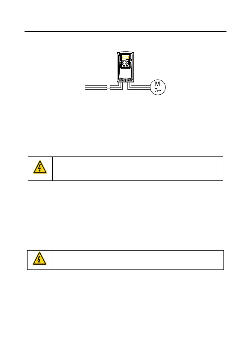
Arrange the protection according to the following guidelines.
Fig 4-25 Fuse configuration
Note: Select the fuse as the manual indicated. The fuse will protect the input power cable from
damage in short-circuit situations. It will protect the surrounding devices when the internal of the VFD
is short circuited.
4.5.2 Protecting the motor and motor cable in short-circuit situations
The VFD protects the motor and motor cable in a short-circuit situation when the motor cable is
dimensioned according to the rated current of the VFD. No additional protection devices are needed.
If the VFD is connected to multiple motors, a separate thermal overload switch or
a circuit breaker must be used for protecting each cable and motor. These
devices may require a separate fuse to cut off the short-circuit current.
4.5.3 Protecting the motor against thermal overload
According to regulations, the motor must be protected against thermal overload and the current must
be switched off when overload is detected. The VFD includes a motor thermal protection function that
protects the motor and closes the output to switch off the current when necessary.
4.5.4 Implementing a bypass connection
It is necessary to set power frequency and variable frequency conversion circuits for the assurance of
continuous normal work of the VFD if faults occur in some significant situations.
In some special situations, for example, if it is only used in soft start, the VFD can be converted into
power frequency running after starting and some corresponding bypass should be added.
Never connect the supply power to the VFD output terminals U, V and W. Power
line voltage applied to the output can result in permanent damage to the VFD.
If frequent shifting is required, employ mechanically connected switches or contactors to ensure that
the motor terminals are not connected to AC power line and VFD output terminals simultaneously.

 Loading...