Goodrive35 Series Closed-loop Vector Control VFD Communication protocol
230
Note: Some parameters in the preceding table are valid only after they are enabled. Take the running
and stop operations as examples, you need to set "Running command channel" (P00.01) to
"Communication", and set "Communication running command channel" (P00.02) to the Modbus
communication channel. For another example, when modifying "PID setting", you need to set "PID
reference source" (P09.00) to Modbus communication.
The following table describes the encoding rules of device codes (corresponding to the identification
code 2103H of the VFD).
10.4.6 Fieldbus ratio values
In practical applications, communication data is represented in the hexadecimal form, but
hexadecimal values cannot represent decimals. For example, 50.12 Hz cannot be represented in the
hexadecimal form. In such cases, we can multiply 50.12 by 100 to obtain an integer 5012, and then
50.12 can be represented as 1394H (5012 in the decimal form) in the hexadecimal form.
In the process of multiplying a non-integer by a multiple to obtain an integer, the multiple is referred to
as a fieldbus scale.
The fieldbus scale depends on the number of decimals in the value specified in "Detailed parameter
description" or "Default value". If there are n decimals in the value, the fieldbus scale m is the
n
th
-power of 10. Take the following table as an example, m is 10.
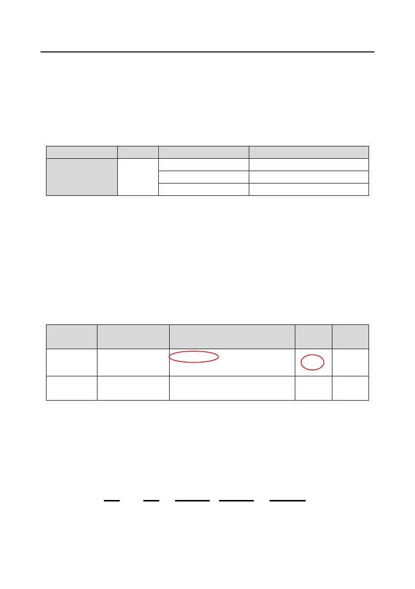
Detailed parameter description
Hibernation restore
delay time
0.0–3600.0s (valid when P01.19 is
2)
0: Restart is disabled
1: Restart is enabled
The value specified in "Detailed parameter description" or "Default value" contains one decimal, so
the fieldbus scale is 10. If the value received by the upper computer is 50, the value of
"Wake-up-from-sleep delay" of the VFD is 5.0 (5.0=50/10).
To set the "Wake-up-from-sleep delay" to 5.0s through Modbus communication, you need first to
multiply 5.0 by 10 according to the scale to obtain an integer 50, that is, 32H in the hexadecimal form,
and then transmit the following write command:
VFD
address
Write
command
Parameter
address
Parameter
data
CRC check
01 06 01 14 00 32 49 E7