Goodrive35 Series Closed-loop Vector Control VFD Optional peripheral accessories
284
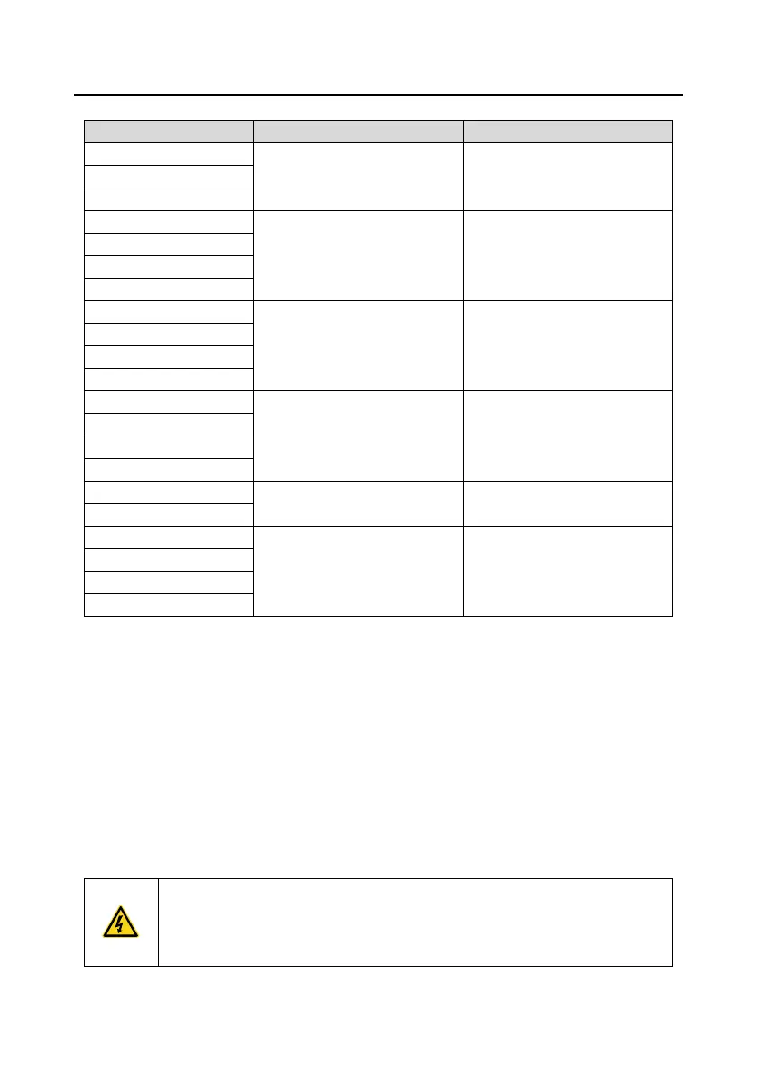
D.7.3 Filters for AC 3PH 520 V (-15%)–690 V (+10%)
Note:
1. The input EMI meets the C2 requirements after an input filter is configured.
2. The preceding table describes external accessories. You need to specify the ones you choose
when purchasing accessories.
D.8 Brake system
D.8.1 Selecting the brake components
When a VFD driving a high-inertia load decelerates or needs to decelerate abruptly, the motor runs in
the power generation state and transmits the load-carrying energy to the DC circuit of the VFD,
causing the bus voltage of the VFD to rise. If the bus voltage exceeds a specific value, the VFD
reports an overvoltage fault. To prevent this from happening, you need to configure brake
components.
The design, installation, commissioning, and operation of the device must be
performed by trained and qualified professionals.
Follow all the "Warning" instructions during the operation. Otherwise, major
physical injuries or property loss may be caused.

 Loading...