Goodrive35 Series Closed-loop Vector Control VFD Optional peripheral accessories
285
Only qualified electricians are allowed to perform the wiring. Otherwise, damage
to the VFD or brake components may be caused.
Read the brake resistor or unit instructions carefully before connecting them to
the VFD.
Connect brake resistors only to the terminals PB and (+), and brake units only to
the terminals (+) and (-). Do not connect them to other terminals. Otherwise,
damage to the brake circuit and VFD and fire may be caused.
Connect the brake components to the VFD according to the wiring diagram. If the
wiring is not properly performed, damage to the VFD or other devices may be
caused.
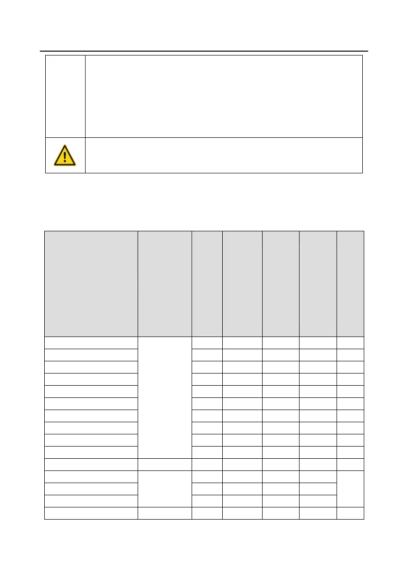
D.8.1.1 Brake units for AC 3PH 380 V (-15%)–440 V (+10%)
Goodrive350 series VFDs of 380 V, 37 kW or lower are equipped with built-in brake units, and those
of 380 V, 45 kW or higher need to be configured with external brake units. Select brake resistors
according to the specific requirements (such as the brake torque and brake usage requirements) on
site.
Brake
resistor
value
matched
with
100%
brake
torque
(Ω)
Dissipation
power of
brake
resistor
(kW)
(10%
brake)
Dissipated
power of
brake
resistor
(kW)
(50%
brake)
Dissipated
power of
brake
resistor
(kW)
(80%
brake)
Min
allowed
brake
resistor
(Ω)

 Loading...