Goodrive35 Series Closed-loop Vector Control VFD Installation guide
26
PB and (+) are connected with the terminals of
brake resistor.
380 V: the grounding resistor is
less than 10Ohm
Protective grounding terminals, every machine is
provided 2 PE terminals as the standard
configuration. These terminals should be grounded
with proper techniques.
660 V: the grounding resistor is
less than 10Ohm
Control power supply terminal
Optional for the VFDs of 380 V, standard for the
VFDs of 660 V (with external 220 V control power)
If no voltage is present on the main circuit, more
convenient and safer commissioning is available
through the auxiliary power supply.
Note:
1. Do not use an asymmetrically constructed motor cable. If there is a symmetrically constructed
grounding conductor in the motor cable in addition to the conductive shield, connect the grounding
conductor to the grounding terminal at the VFD and motor ends.
2. Brake resistor, brake unit and DC reactor are optional parts.
3. Route the motor cable, input power cable and control cables separately.
4. If the terminal description is "/", the machine does not provide the terminal as the external terminal.
4.3.3 Wiring of terminals in main circuit
1. Connect the ground wire of the input power cable to the ground terminal (PE) of the VFD, and
connect the 3PH input cable to the terminals R, S, and T, and fasten them up.
2. Connect the ground wire of the motor cable to the ground terminal of the VFD, and connect the
3PH motor cable to the terminals U, V, and W, and fasten them up.
3. Connect the brake resistor and other accessories that are equipped with cables to the specified
positions.
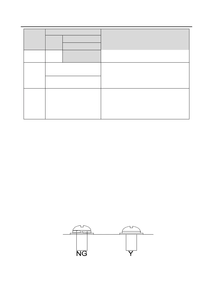
4. Fasten all the cables outside of the VFD mechanically, if possible.
The screw is not fastened The screw is not fastened
Figure 4-19 Diagram of screw installation

 Loading...