Goodrive35 Series Closed-loop Vector Control VFD Extension card
244
Transmission line parameters:
Capacitance per unit length (pF/m)
Line-core cross-section (mm
2
)
Besides shielding twisted-pair copper wires, PROFIBUS can also use optical fiber for transmission in
an electromagnetic interference environment to increase the high-speed transmission distance there
are two kinds of fiber optical conductors, one is low-cost plastic fiber conductor, used distance is less
than 50 meters, the other is glass fiber conductor, and used distance is less than 1 km.
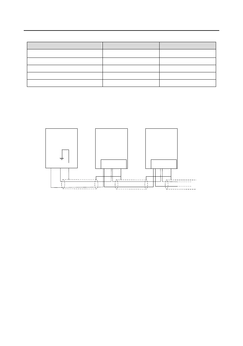
A.2.6.5 PROFIBUS bus connection diagram
INVT VFD
CH-PA01 adapter
INVT VFD
PROFIBUS
master station
A
B
SHLD
A
B
SHLD
A
B
GND
CH-PA01 adapter
Above is "terminal" wiring diagram. Cable is a standard PROFIBUS cable consisting of a twisted pair
and shielding layer. The shielded layer of PROFIBUS cable on all nodes is directly grounded. Users
can choose the best grounding method according to the situation.
Note:
1. Make sure that signal lines do not twist when connecting all stations. Shielded cable should be
used when system runs under high electromagnetic interface environment, which can improve
electromagnetic compatibility (EMC).
2. If using shielded braided wire and shielding foil, both ends should be connected to ground. Using
shielding area should be large enough to maintain a good conductivity. And data lines must be
separated from high-voltage.
3. Stub line segment should not be used when transmission rate more than 500K bit/s, The plug is
available on the market which connects directly to data input and output cable. Bus plug connection
can be on or off at any time without interruption of data communications of other station.
A.2.7 System configuration
1. System configuration

 Loading...