Goodrive35 Series Closed-loop Vector Control VFD Extension card
241
700W/m
2
, air pressure 70–106kPa
● Content of salt spray and corrosive gases: Pollution degree 2
● Dust and solid particles content: Pollution degree 2
● Vibration and shock: 5.9m/s
2
(0.6g) on 9–200 Hz sinusoidal vibration
2. Installation steps:
● Fix the communication card on the location holes with screws.
● Insert the communication card into the defined location carefully and fix it on the copper column with
screw.
● Set the bus terminal switch of the communication card to the needed location.
3. Notes:
Disconnect the device from the power line before installation. Wait for at least three minutes to let the
capacitors discharge. Cut off dangerous voltage from external control circuit to the unit output and
input terminals.
Some electric components are sensitive to static charge. Do not touch the circuit board. If you have to
operate on it, please wear the grounding wrist belt.
A.2.6.2 Electrical installation of EC-TX-103 communication card
1. Node selection
Node address is the only address of PROFIBUS bus. The address which is among 00–99 is shown
with two figures and is selected by the spinning switch on the module. The left switch shows the first
number and the right one show the second number.
Node address = 10 x the first digital value + the second digital value x 1
2. Bus terminals
There is a bus terminal in each heading and ending to avoid error during operation. The DIP switch on
RPBA-01PCB is used to connect the bus terminals which can avoid the signal feedback from the bus
cables. If the module is the first or last one in the internet, the bus terminal should be set as ON.
Please disconnect EC-TX-103 communication card terminals when the PROFIBUS D-sub connector
with internal terminals is in use.
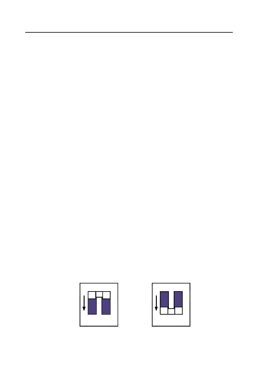
Fieldbus terminal ON
ON
Fieldbus terminal OFF
ON

 Loading...