IPE300 series engineering VFD Basic operation guidelines
-90-
Input terminal status at
present fault
Digital input terminal
status
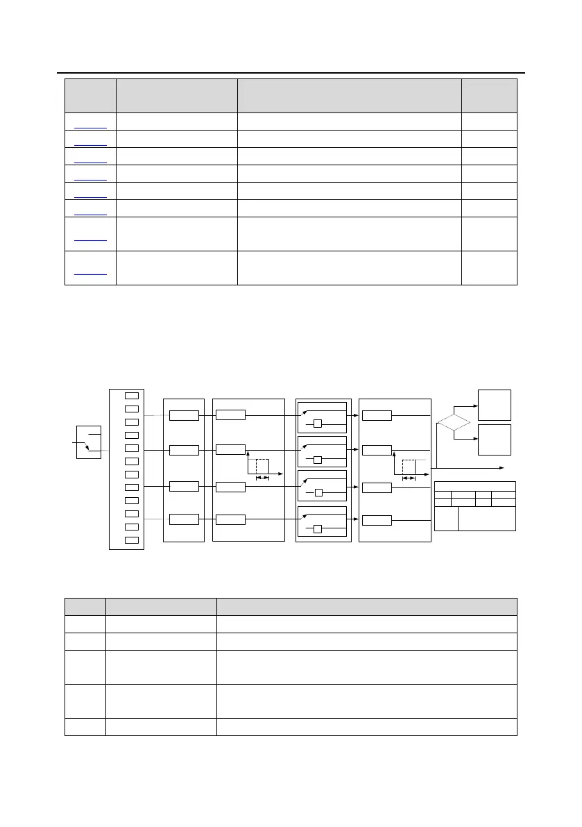
5.5.12 Digital output
The VFD carries two groups of relay output terminals, one open collector Y output terminal and one
high-speed pulse output (HDO) terminal. The function of all the digital output terminals can be
programmed through function codes, of which the high-speed pulse output terminal HDO can also be
set to high-speed pulse output or digital output by function code.
0
1
2
3
4
5
.
.
.
.
29
30
P06.01
P06.03
P06.04
P06.02
T delay
T delay
T delay
T delay
0
1
P06.05 output polarity
selection
(Default value: 0)
(Default value: 0)
(Default value: 1)
(Default value: 5)
P06.00
HDO
input type
0
1
0
1
0
1
delay
0
1
-1
-1
-1
-1
P17.12
Digital input
terminal state
P07.40
Digital output
terminal state
of current fault
Fault?
Fault
Run
Y BIT0 HDO BIT1
ROI BIT2 RO2 BIT3
P06.05, P17.12, P07.40 display
P06.00
0: Open collector high-
speed pulse output
1: Open collector output
P06.07
P06.09
P06.11
P06.13
Y
RO2
ROI
HDO
Digital switch-off delay
Digital output selection
T delay
T delay
T delay
T delay
delay
P06.06
P06.08
P06.10
P06.12
Digital switch-on delay
The following table lists the function code options. A same output terminal function can be repeatedly
selected.
The output terminal does not have any function.
Output ON signal when there is frequency output during running
Output ON signal when there is frequency output during forward
running
Output ON signal when there is frequency output during reverse
running
Output ON signal when there is frequency output during jogging
 Loading...


