IPE300 series engineering VFD Installation guidance
-22-
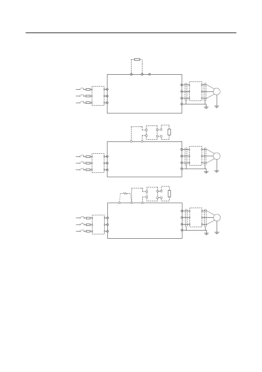
4.3 Standard wiring of the main circuit
4.3.1 Wiring diagram of the main circuit
0037 and lower
0045-0110 (inclusive)
0132 and higher
Braking resistor
Braking unit
Braking resistor
Braking resistor
Braking unit
Input
reactor
Input
filter
Fuse
Input
reactor
Input
filter
3-phase power
380V(-15%) ~
440V(+10%)
50/60Hz
R
S
T
R
S
T
U
V
W
PE
U
V
W
PE
Output
reactor
Output
filter
M
(+) (-)
P1
(+) (-)
PB
Fuse
Fuse
Input
reactor
Input
filter
R
S
T
U
V
W
PE
Output
reactor
Output
filter
Output
reactor
Output
filter
M
M
(+) (-)
DC+
DC-
DC+
DC-
DC reactor
3-phase power
380V(-15%) ~
440V(+10%)
50/60Hz
3-phase power
380V(-15%) ~
440V(+10%)
50/60Hz
Figure 4-7 Main circuit wiring diagram for AC 3PH 380V(-15%)–440V(+10%)
Note:
The fuse, DC reactor, braking unit, braking resistor, input reactor, input filter, output reactor and
output filter are optional parts. For details, see “Appendix D Optional peripheral accessories".
P1 and (+) have been short connected by default for the 380V 0132 and higher VFD models. If
you need to connect to an external DC reactor, take off the short-contact tag of P1 and (+).
Before connecting the braking resistor, remove the yellow warning label with PB, (+) and (-) from
the terminal block; otherwise, poor contact may occur.
Built-in braking unit is optional for the 380V 0045 -0110 VFD models.
 Loading...


