IPE300 series engineering VFD Extension card
-308-
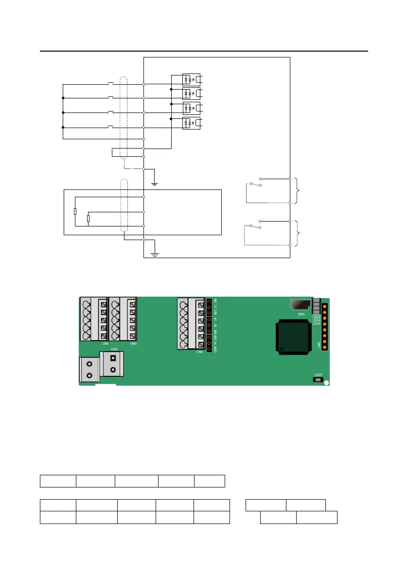
+24V
PE
COM
S6
S5
PW
Extended terminal S5
Extended terminal S6
PT1+
PT2+
PT-
PE
(External temperature
resistor)
IPE300 series expansion card
RO4C
RO4A
RO3C
RO3A
Relay output 3
Relay output 4
Temperature input
Extended terminal S7
Extended terminal S8
S8
S7
Figure A-5 Control circuit wiring diagram of I/O card 2
A.6 Programmable extension card (EC-PC502-00)
In this figure, SW1 is the start/stop switch of the programmable extension card. CN1 contains
terminals PE, 485-, 485+, GND, AI1, and AO1, and a selection jumper resides on the next. "AI" and
"AV" are the current type input selection and voltage type input selection of AI1, and they can be
selected through J2. "AIO" and "AVO" are the current type output selection and voltage type output
selection of AO1, and they can be selected through J5. "120" indicates 120Ω terminal resistor, and it
can connect to J1. By default, J1 connects to NC, J2 to AV, and J5 to AVO. The terminals are
arranged as follows.
 Loading...


