EasyManuals Logo
Home>INVT>DC Drives>IPE300 Series

INVT IPE300 Series User Manual

INVT IPE300 Series
383 pages
To Next Page IconTo Next Page
To Previous Page IconTo Previous Page
Page #232 background imageLoading...
Page #232 background image
IPE300 series engineering VFD Function parameter list
-221-
P25 group––I/O card input functions
Function
code
Name
Description
Default
Modify
P25.00
HDI3 input type
0: HDI3 is high-speed pulse input
1: HDI3 is digital input
0
â—Ž
P25.01
Function of S5
Same as P05 group
0
â—Ž
P25.02
Function of S6
0
â—Ž
P25.03
Function of S7
0
â—Ž
P25.04
Function of S8
0
â—Ž
P25.05
Function of S9
0
â—Ž
P25.06
Function of S10
0
â—Ž
P25.07
Function of HDI3
0
â—Ž
P25.08
Input terminal
polarity of
extension cards
0x00–0x7F
0x00
â—‹
P25.09
Virtual terminal
setting of
extension cards
0x000–0x7F (0: disable; 1: enable)
BIT0: S5 virtual terminal
BIT1: S6 virtual terminal
BIT2: S7 virtual terminal
BIT3: S8 virtual terminal
BIT4: S9 virtual terminal
BIT5: S10 virtual terminal
BIT6: HDI3 virtual terminal
0x00
â—Ž
P25.10
HDI3 switch-on
delay
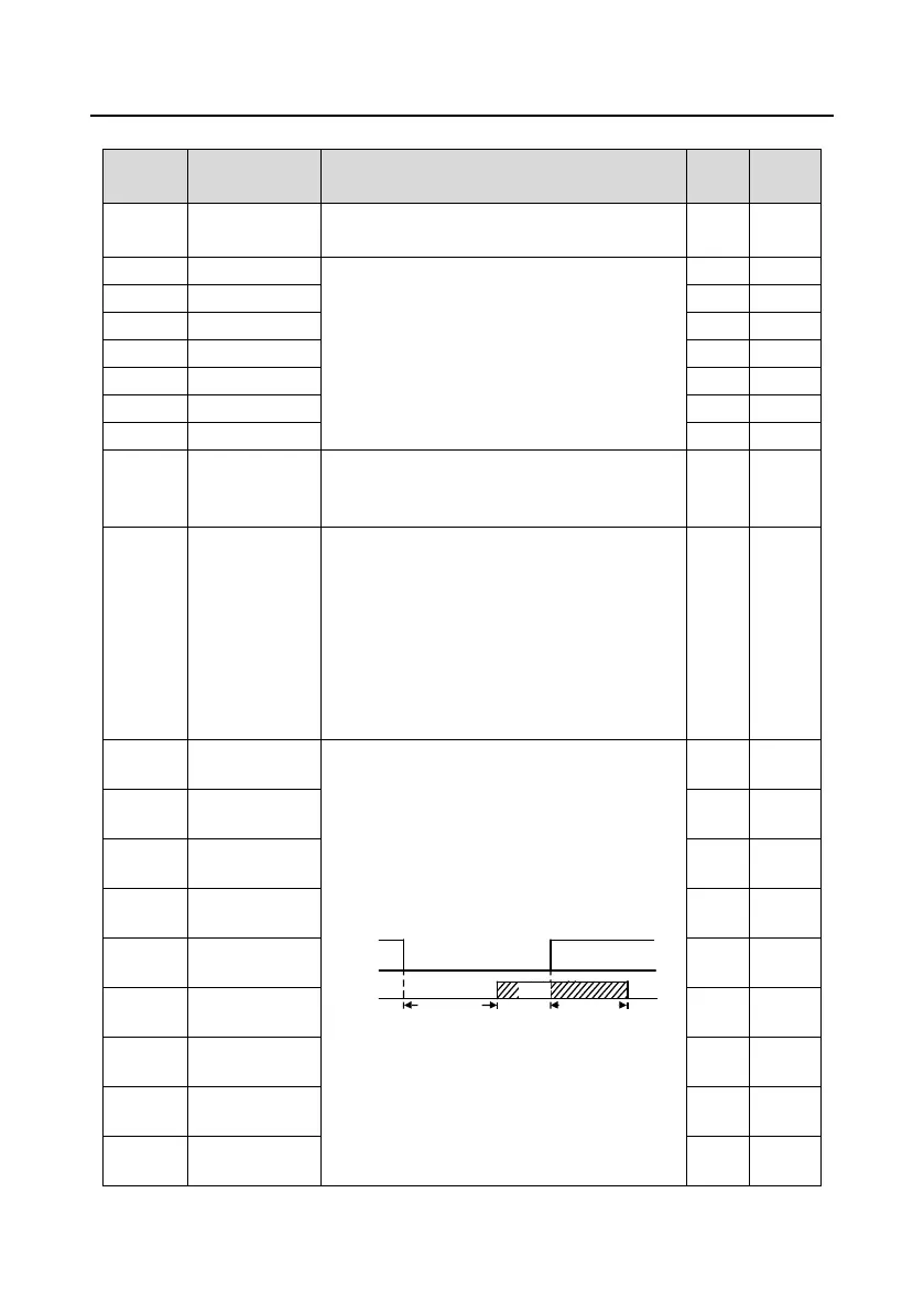
Used to specify the delay time corresponding to
the electrical level changes when the
programmable input terminals switch on or switch
off.
Si electrical level
Si valid
invalid invalid
Switch-on
delay
Switch-off
delay
valid
Setting range: 0.000–50.000s
0.000s
â—‹
P25.11
HDI3 switch-off
delay
0.000s
â—‹
P25.12
S5 switch-on
delay
0.000s
â—‹
P25.13
S5 switch-off
delay
0.000s
â—‹
P25.14
S6 switch-on
delay
0.000s
â—‹
P25.15
S6 switch-off
delay
0.000s
â—‹
P25.16
S7 switch-on
delay
0.000s
â—‹
P25.17
S7 switch-off
delay
0.000s
â—‹
P25.18
S8 switch-on
delay
0.000s
â—‹

Table of Contents

Questions and Answers:

Question and Answer IconNeed help?

Do you have a question about the INVT IPE300 Series and is the answer not in the manual?

INVT IPE300 Series Specifications

General IconGeneral
BrandINVT
ModelIPE300 Series
CategoryDC Drives
LanguageEnglish

Related product manuals