IPE300 series engineering VFD Extension card
-301-
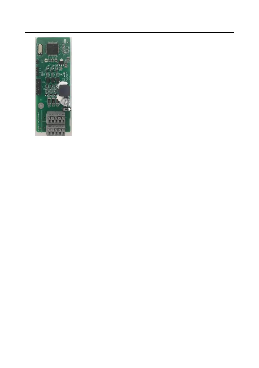
Simplified incremental
PG card
EC-PG507-12
A.2 Dimensions and installation
All extension cards are of the same dimensions (108x39mm) and can be installed in the same way.
Comply with the following rules when installing or removing an extension card:
1. Ensure that no power is applied before installing the extension card.
2. The extension card can be installed in any one of the SLOT1, SLOT2, and SLOT3 card slots.
3. The 5.5 kW and lower VFD models can be configured with two extension cards at the same time,
and the 7.5 kW and higher VFD models can be configured with three extension cards.
4. If interference occurs on the external wires after extension cards are installed, change their
installation card slots flexibly to facilitate the wiring. For example, the connector of the connection
cable of the DP card is large, so it is recommended to be installed in the SLOT1 card slot.
5. To ensure high anti-interference capability in closed-loop control, you need to use a shielding
wire in the encoder cable and ground the two ends of the shielding wire, that is, connect the
shielding layer to the housing of the motor on the motor side, and connect the shielding layer to
the PE terminal on the PG card side.
 Loading...


