IPE300 series engineering VFD Product overview
-8-
3 Product overview
3.1 What this chapter contains
This chapter mainly introduces the operation principles, product features, layouts, nameplates and
model designation rules.
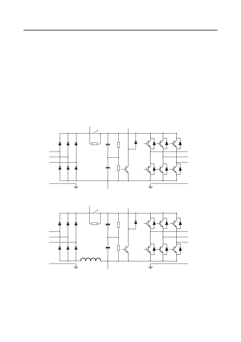
3.2 Basic principles
The VFD is used to control asynchronous AC induction motor and permanent-magnet synchronous
motor. The following figure shows the main circuit diagram of the VFD.
The rectifier converts 3PH AC voltage into DC voltage, and the capacitor bank of intermediate circuit
stabilizes the DC voltage. The inverter converts DC voltage into AC voltage that can be used by an
AC motor. When the circuit voltage exceeds the maximum limit value, external braking resistor will be
connected to intermediate DC circuit to consume the feedback energy.
Figure 3-1 380V (0015 and lower) main circuit diagram
Figure 3-2 380V (0018–0037) main circuit diagram
 Loading...


