IPE300 series engineering VFD Installation guidance
-27-
Grounding terminal for safe protection
Grounding terminal for safe
protection; each machine must carry
two PE terminals and proper
grounding is required
Control power terminals (connects to 220V
external control power)
These terminals are a standard
configuration for 660V models. For
380V 0004 and higher models, they
are optional and can be purchased
when ordering the VFDs. With these
terminal, the VFD can be energized
by auxiliary power without powering
up the input main circuit for easier
and safer commissioning.
Note:
Do not use asymmetrical motor cables. If there is a symmetrical grounding conductor in the motor
cable besides the conductive shielded layer, ground the grounding conductor on the VFD end
and motor end.
Braking resistor, braking unit and DC reactor are optional parts.
Route the motor cable, input power cable and control cable separately.
"Not available" means this terminal is not for external connection.
4.3.3 Wiring procedure of main circuit terminals
1. Connect the grounding line of the input power cable to the grounding terminal (PE) of the VFD,
and connect the 3PH input cable to R, S and T terminals and tighten up.
2. Connect the grounding line of the motor cable to the PE terminal of the VFD, connect the 3PH
cable of the motor to the U, V, and W terminals of the VFD, and tighten up.
3. Connect the brake resistor and other options with cable to the specified position.
4. If allowed, fix all the cables at the outside of the VFD mechanically.
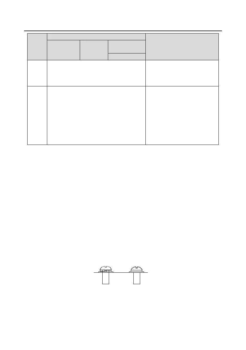
The screw is
not fastened.
The screw is
fastened.
YNG
Figure 4-17 Screw installation diagram
 Loading...


