IPE300 series engineering VFD Optional peripheral accessories
-350-
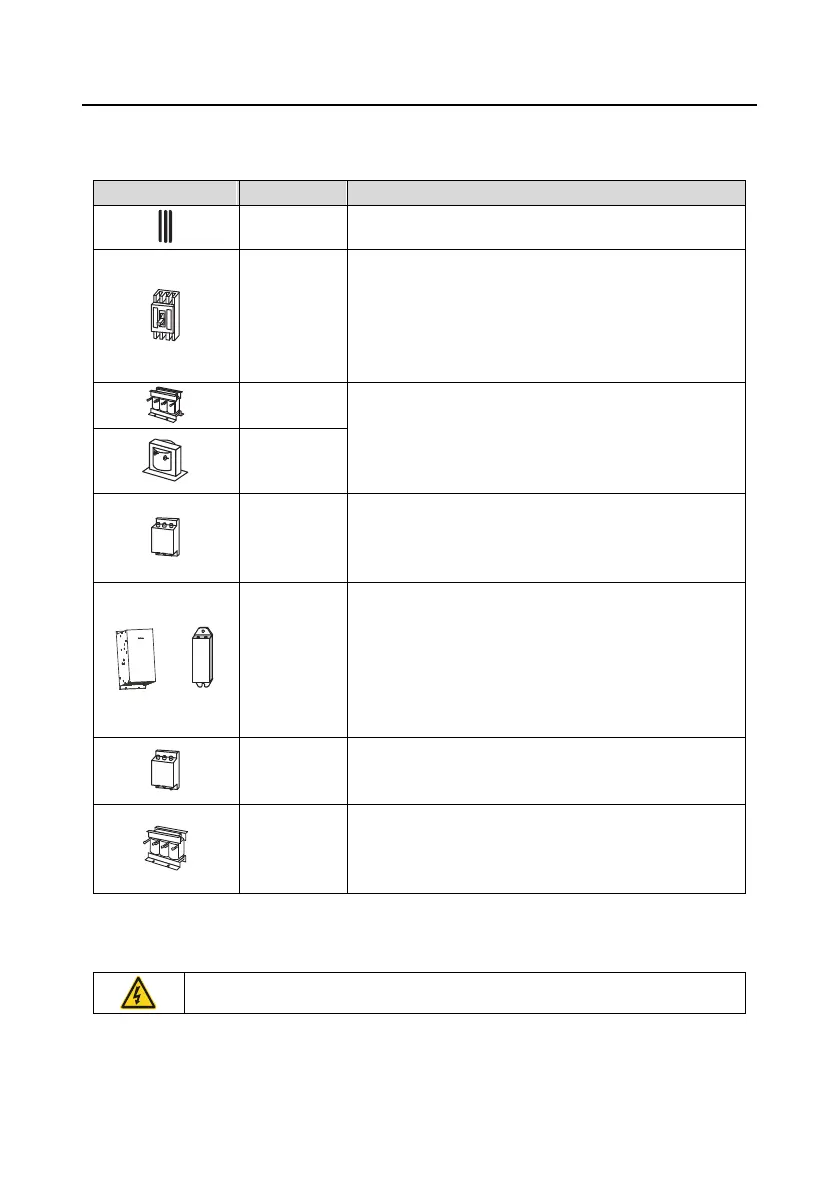
The braking units are INVT DBU series standard braking units. For details, see the DBU
operation manual.
Accessory for signal transmission.
Device for electric shock prevention and protection against
short-to-ground that may cause current leakage and fire.
Select residual-current circuit breakers (RCCBs) that are
applicable to VFDs and can restrict high-order harmonics,
and of which the rated sensitive current for one VFD is
larger than 30 mA.
Accessories used to improve the power factor on the input
side of the VFD, and thus restrict high-order harmonic
currents.
VFD of 380V 0132 or higher and 660V series can be
directly connected to external DC reactors.
Accessory that restricts the electromagnetic interference
generated by the VFD and transmitted to the public grid
through the power cable. Try to install the input filter near
the input terminal side of the VFD.
Braking unit or
braking
resistor
Accessories used to consume the regenerative energy of
the motor to reduce the DEC time.
VFDs of 380V 0037 or lower need only to be configured
with braking resistors, those of 380V 0132 or higher and
660V series also need to be configured with braking units,
and those of 380V 0045–0110 to 110kW can be configured
with optional built-in braking units.
Accessory used to restrict interference generated in the
wiring area on the output side of the VFD. Try to install the
output filter near the output terminal side of the VFD.
Accessory used to lengthen the valid transmission distance
of the inverter, which effectively restrict the transient high
voltage generated during the switch-on and switch-off of the
IGBT module of the inverter.
D.3 Power supply
See section “Installation guidance”.
Ensure that the voltage class of the VFD is consistent with that of the grid.
 Loading...


