Due to friction force, it is required to set certain
identification torque for the inertia identification to
be performed properly.
0.0–100.0% (of the rated motor torque)
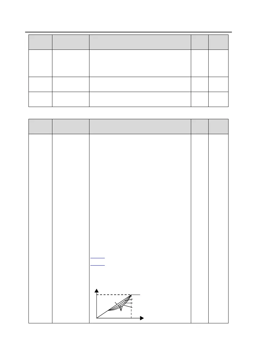
This group of function code defines the V/F curve
of motor 1 to meet the needs of different loads.
0: Straight-line V/F curve, applicable to constant
torque loads
1: Multi-point V/F curve
2: Torque-down V/F curve (power of 1.3)
3: Torque-down V/F curve (power of 1.7)
4: Torque-down V/F curve (power of 2.0)
Curves 2 – 4 are applicable to the torque loads
such as fans and water pumps. You can adjust
according to the characteristics of the loads to
achieve best performance.
5: Customized V/F (V/F separation); in this mode,
V can be separated from F and F can be adjusted
through the frequency setting channel set by
P00.06 or the voltage setting channel set by
P04.27 to change the characteristics of the
curve.
Note: In the following figure, V
b
is the motor rated
voltage and f
b
is the motor rated frequency.
Output voltage
Output frequency
Linear type
Square type
Torque step-down V/F curve (power of 1.3)
Torque step-down V/F curve (power of 1.7)
Torque step-down V/F curve (power of 2.0)
V
b
f
b
 Loading...


