IPE300 series engineering VFD Basic operation guidelines
-109-
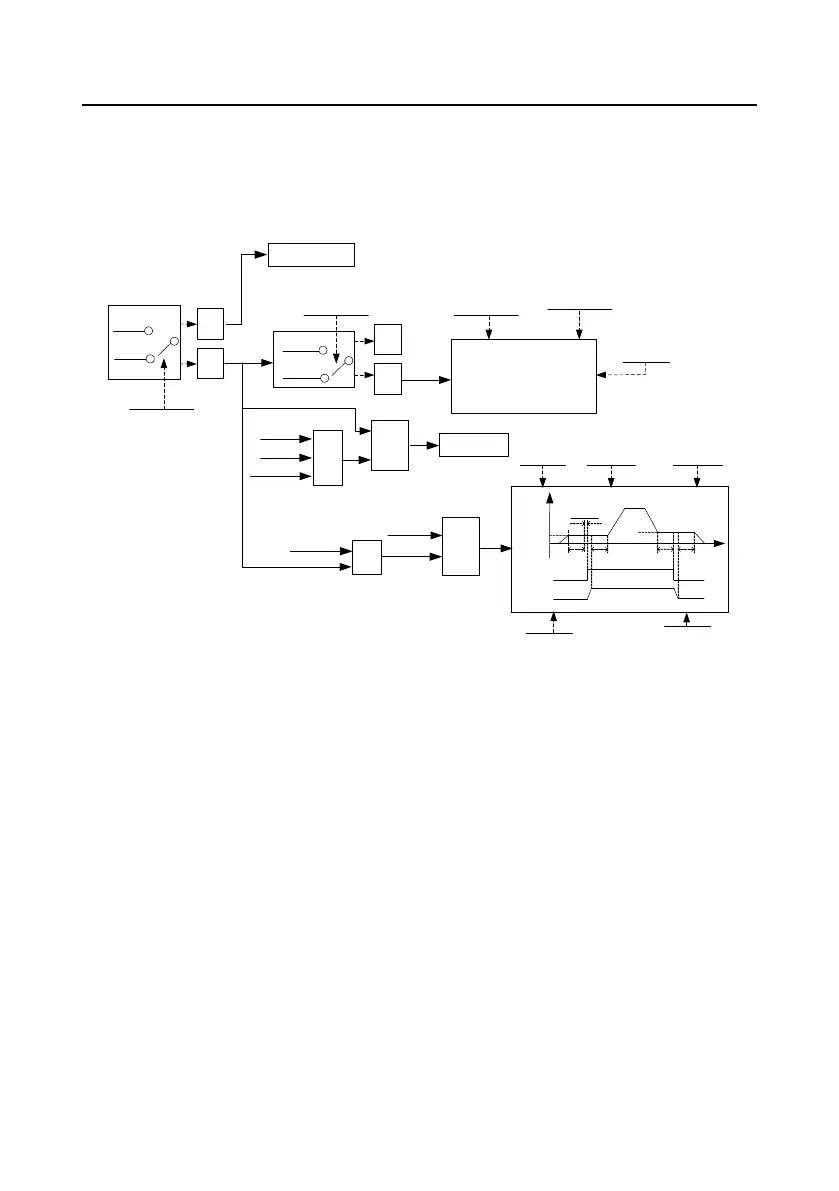
5.5.19 Brake control function
P94 group provides the parameter setting of brake control. When the drive is not active, the brake is
used to protect the drive from undesired movements, such as caused by potential energy loads or
vertical running loads.
See the following figure for its logic principle.
1
0 invalid
valid
P94.00
Brake control mode
=1
=0
Normal mode
Brake fault
detection
P05
group
Brake feedback terminal is valid
External brake
feedback signal
Brake feedback
detection time
P94.09
Fault
≥1
&
Switch-on
command
&
Run
command
&
Torque
verification
Delay time before
brake release
P94.04
f
t
P94.04
Switch on
Brake release
Torque
verification
P94.02
Brake release
frequency
P94.02
Delay time after
brake release
P94.05
P94.06
OFF2
P94.07 P94.08
Brake
command
Brake
action
P94.08
Delay time after brake
switch-on
Braking frequency
P94.06
Coast to stop
1
0
No
feedback
With
feedback
P94.01
Brake feedback mode
=1
=0
P94.05
Switch on
Brake release
 Loading...


