IPE300 series engineering VFD Extension card
-317-
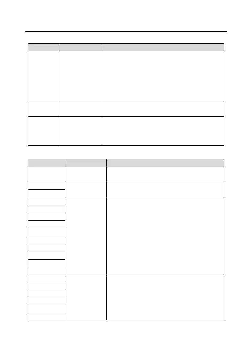
Indicator definition:
This indicator is on when the extension card is establishing a
connection with the control board;
it blinks periodically after the extension card is properly
connected to the control board (the period is 1s, on for 0.5s,
and off for the other 0.5s);
and it is off when the extension card is disconnected from
the control board.
This indicator is on after the control board feeds power to the
PG card.
This indicator is off when A1 and B1 of the encoder are
disconnected; it blinks when C1 and D1 of the encoder are
disconnected; and it is on when the encoder signals are
normal.
EC-PG502 terminal function description:
It is connected to the ground for enhancing the
anti-interference performance.
Voltage: 5V ± 5%
Max. output current: 150mA
1. Supporting Sin/Cos encoders (with CD signal or
without CD signal)
2. SINA/SINB/SINC/SIND 0.6–1.2Vpp; SINR
0.2–0.85Vpp
3. Max. frequency response of A/B signals: 200 kHz
Max. frequency response of C/D signals: 1 kHz
1. Differential input of 5 V
2. Response frequency: 200 kHz
 Loading...


