Rev. 2.0
Maintenance Guide
1-42
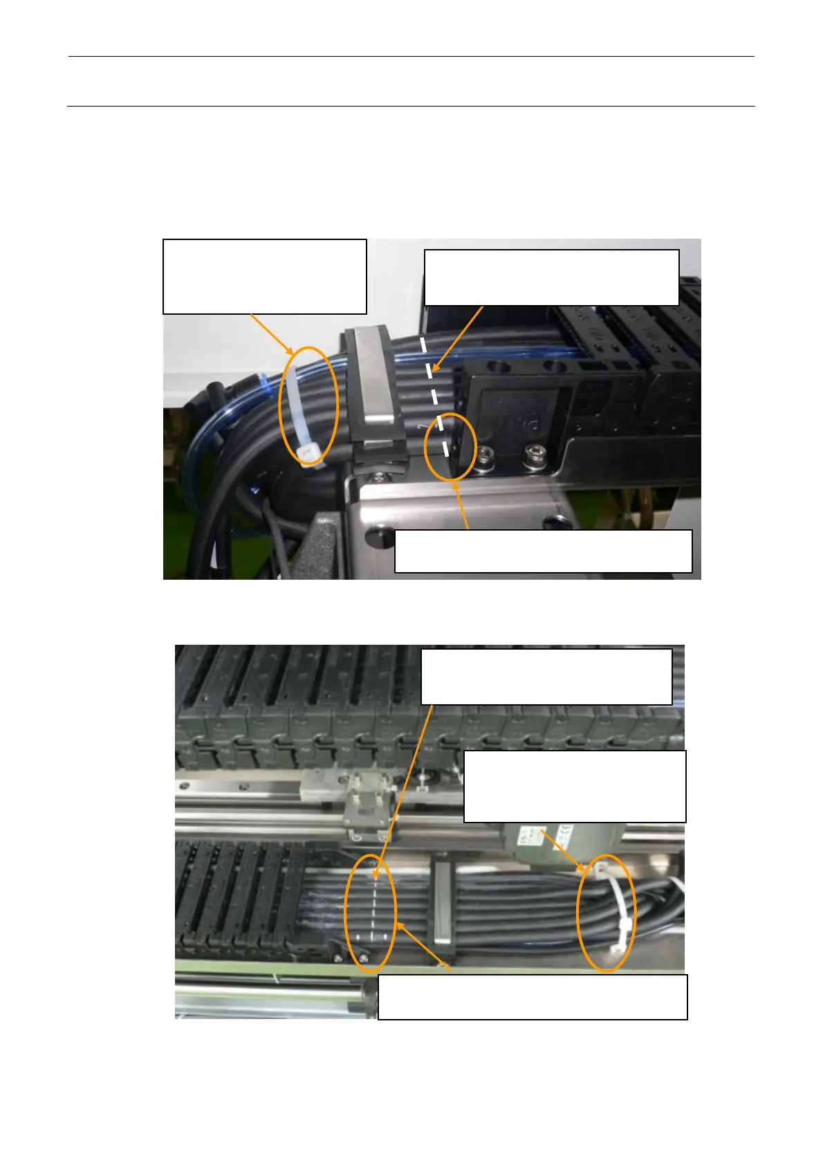
3) Arrange the relay connectors (CN127, CN151, CN165, CN201, CN245, CN813, ZTPWR1,
ZTPWR2) of the connector brackets of the Y veyor-cable (Y veyor-cable XL) and XY
veyor-cable (XY veyor-cable XL).
Adjust the end (rear) of the cable clamp to the white marking on the Y veyor-cable, and then
secure the cables.
Put the white marking on the XY veyor-cable along the end (rear) of the cable clamp.
XY VEYOR-CABLE ASM
1394 ROBOT CABLE
OPTICAL FIBER CABLE
Figure 1-6-6-2-1 M and L Board Specifications
Figure 1-6-6-2-2 XL Board Specifications
7M
Air tube
Put the white marking at the end of the
Y-cableveyor of the XY veyor-cable
(40113621).
Adjust the white marking on the Y VEYOR-CABLE
ASM (40113623) to the end of the Y-cableveyor.
Adjust the white marking on the Y VEYOR-CABLE
XL ASM (40092638) to the end of the Y-cableveyor.
Put the white marking at the end of the
Y-cableveyor of the XY veyor-cable
(40113621).
XY VEYOR-CABLE ASM
1394 ROBOT CABLE
OPTICAL FIBER CABLE 6.5M
Air tube
 Loading...


